THE CUTTING EDGE
The Diagnostic Advantage of a CBCT-Derived Segmented STL Rendition of the Teeth and Jaws Using an AI Algorithm
This column is compiled by JCO Technology Editor Marc S. Lemchen, DMD. To help keep our readers on The Cutting Edge, Dr. Lemchen will spotlight a particular area of orthodontic technology every few months. Your suggestions for future subjects or authors are welcome.
Imagine reviewing with a parent a cone-beam computed tomography (CBCT) image that shows an impacted canine impinging on the root of a lateral incisor. Most of us would explain the risks of the lateral incisor root being damaged, perhaps by showing other examples of lateral incisor resorption. Now imagine being able to virtually remove the patient’s lateral incisor from the CBCT image and get a single three-dimensional image of the lateral incisor that can be rotated 360°, showing the damage to the root that has already occurred. Clearly, a picture that is worth a thousand words.
Over the past 10 years, we have seen our profession increasingly impacted by the application of artificial intelligence (AI), which helps us perform tasks that would be time-consuming—or in some cases impossible—for an individual to accomplish manually.
The following article describes the use of AI to segment individual teeth from a CBCT scan. The file is first converted from Digital Imaging and Communication in Medicine (DICOM) data to standard tessellation language (STL), like the information we get from our optical scanners. This conversion allows the program to use AI algorithms to virtually “extract” individual teeth for closer examination. We now can clearly see, instead of inferring, the amount of resorption that has resulted from an erupting canine contacting a lateral incisor root.
Nowhere is visualization more helpful than when we are trying to communicate the rationale for treatment, or for a particular treatment plan, to a patient or parent. We take for granted how digital imaging and panoramic and 3D radiographs have facilitated our doctor-to-patient communication over the past 40 years. Think of how easily patients can visualize their teeth on panoramic radiographs, as opposed to a full-mouth series.
Similar articles from the archive:
We can expect to see more and more applications of AI in our daily lives and in the orthodontic profession. AI will certainly affect the efficiency, accuracy, and quality of our orthodontic results. The application described in this article is another step forward in using AI to improve our treatment plans, treatment outcomes, and patient and parent communication.
MSL
The Diagnostic Advantage of a CBCT-Derived Segmented STL Rendition of the Teeth and Jaws Using an AI Algorithm
An accurate diagnosis is the key to a successful orthodontic treatment plan and, consequently, a successful treatment outcome. In today’s profession, this cannot be achieved without appropriate imaging.1
The goal of imaging in medicine and dentistry, including orthodontics, is to display the patient’s “anatomic truth.” For many years, two-dimensional radiographs were used to evaluate the patient’s 3D status.2 The use of 2D x-rays to analyze 3D structures has well-known limitations, however, including magnification, geometric distortion, superimposition of adjacent structures, projective displacement, rotational errors, and linear projective transformation.3,4
Since its introduction to dentistry in 1998, CBCT has changed the diagnostic approach in both dentistry and orthodontics, providing accurate high-resolution 3D imaging from compact and affordable equipment. In addition, it exposes the patient to a significantly lower radiation dose compared with conventional CT.5,6
Digital Process
CBCT is best described as “volumetric imaging.” An x-ray source and detector rotate in a cylindrical or spherical path around the center of the region of interest, with a single rotational sweep of 180-720° creating the field of view. Several hundred 2D images are generated in a procedure that takes 10-40 seconds. These images are processed by the computer to create rectangular cubes called voxels, which are .076-.4mm in size and equal in width, thickness, and height. Each voxel represents a shade of gray, depending on its x-ray absorption. Typically, one scan contains more than 100 million voxels. After the creation of a volumetric database from these voxels, different cross-sections can be produced in all planes of space (sagittal, coronal, and axial), in addition to curved cross-sections (such as panoramic images) and volume renderings (such as cephalometric images).6-9
The 3D medical imaging data produced by the CBCT are stored and transmitted in the form of DICOM files. These files contain the raw data that become the basis for further manipulation.10 The DICOM file can display a series of 2D cross-sections in three planes of space—the most common rendition presented to the examining doctor. The DICOM file can also be segmented, allowing teeth to be removed or hidden so that underlying structures can be exposed. Additionally, the DICOM file can generate a 3D rotating picture of the field of view, including crowns, roots, and bone. The process of distinguishing root from bone is problematic, however, because the two structures are similar in density. Proprietary software programs are available to aid in this procedure, but they are labor-intensive, requiring substantial operator experience and time.11 Even with the required expertise, the full length and anatomy of roots are often compromised or inaccurate. The pathway of the mandibular nerve can be drawn only manually, after examining a large number of 2D slices of the canal track.
To create a user-friendly 3D landscape of the DICOM data, the file should be converted to STL format. STL files, which are used for 3D printing of medical and industrial products, can be viewed on any computer with a standard operating system such as Microsoft Windows.* Automatic STL conversion and segmentation can also be performed from a CBCT DICOM file of the teeth and jaws using an artificial intelligence (AI) program such as CephX,** Anatomage,*** or Imaging Plus.†
AI capabilities have improved significantly since the 1980s and are now becoming important constituents of many medical applications. AI excels at recognizing complex patterns in imaging data, allowing accurate segmentation. In dental radiology, AI can identify the different tissues in a 3D DICOM package obtained from a CBCT scan and automatically convert it to a segmented STL image within minutes.12 In orthodontic diagnosis, since all objects are segmented, the user can see different aspects and easily visualize various “what if” scenarios. For example, “What would the anatomy look like if a tooth were removed?” “Is there a hidden pathology beneath one of the structures?” “What is the spatial relationship between objects?” “Could the 3D interactive model offer better understanding simply by delivering the same information in a new package?”
These AI capabilities are based on deep learning mechanisms,12-14 whereby input is received and the output is learned based on a large, labeled data set that is examined by the AI algorithm at the input level. The data set then undergoes more precise labeling,14 and the AI algorithm is taught to recognize it. Finally, the algorithm’s recognition capabilities are fine-tuned by human intervention (“teaching”) until optimal automatic recognition levels are achieved.
A 3D convolutional neural network is the most common machine-learning method of image recognition and classification.12-14 Besides its uses in medicine and dentistry, it can be applied to such tasks as identification of objects, faces, and traffic signs and for computer vision in self-driving cars. Convolutional neural networks, like neural networks, are made up of perceptrons with learnable weights and biases. Each perceptron receives several inputs, weighs them, and passes the weighted sum through an activation function; it responds with an output, which, in turn, may serve as an input for another perceptron, and so on. In this manner, convolutional neural networks can mimic the decision-making tasks performed by our own central nervous systems.
The following two cases, both treated in the Tel Aviv University Department of Orthodontics, demonstrate how the AI capabilities of DICOM-to-STL conversion can have a significant effect on orthodontic treatment planning.
Case 1
A 13-year-old male presented with a mild dental Class II malocclusion, a bilateral crossbite (upper right first premolar through second molar to lower right first premolar through second molar, and upper left second premolar to lower left second premolar), and a functional shift of the mandible to the right (Fig. 1).
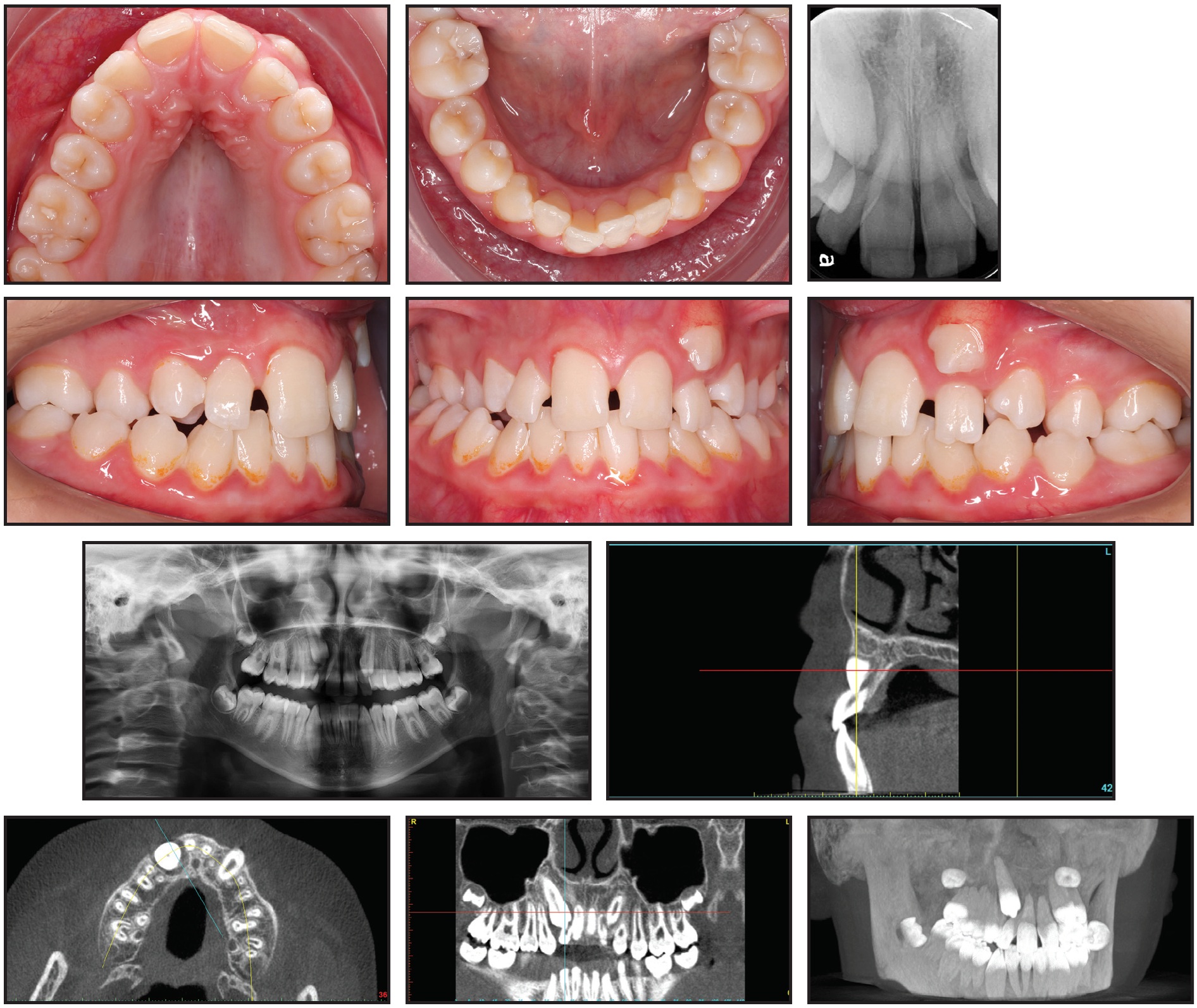
Fig. 1 Case 1. 13-year-old male with mild dental Class II malocclusion, Class I skeletal pattern, and upper and lower crowding before treatment. (Position of upper right canine and integrity of upper lateral incisor roots not apparent on standard x-ray images.)
Clinical examination indicated a Class I skeletal pattern, maxillary constriction, and 9mm of crowding in the upper arch, with a lack of space for the canines; the lower arch showed moderate crowding (5mm). The left maxillary canine had partially erupted in an ectopic position, buccal to the upper left lateral incisor. The upper lateral incisors were buccodistally tipped, and the upper right canine was not palpable buccally or palatally.
The initial evaluation would likely have led to a nonextraction treatment plan including maxillary expansion and some form of arch development to resolve the crowding in both arches and gain enough space for the canines to erupt. There was, however, a radiographic suggestion of root resorption involving both upper lateral incisors. Because the panoramic and periapical x-rays could not clearly confirm the position of the upper right canine nor the integrity of the upper lateral incisor roots, the patient was sent for a CBCT scan.
The DICOM file of the scan was uploaded to the CephX web viewer for automated AI conversion to STL. A 3D segmented model of the teeth and jaws could then be viewed, and the canines and central incisors could be virtually extracted for better visualization of the lateral incisors (Fig. 2).
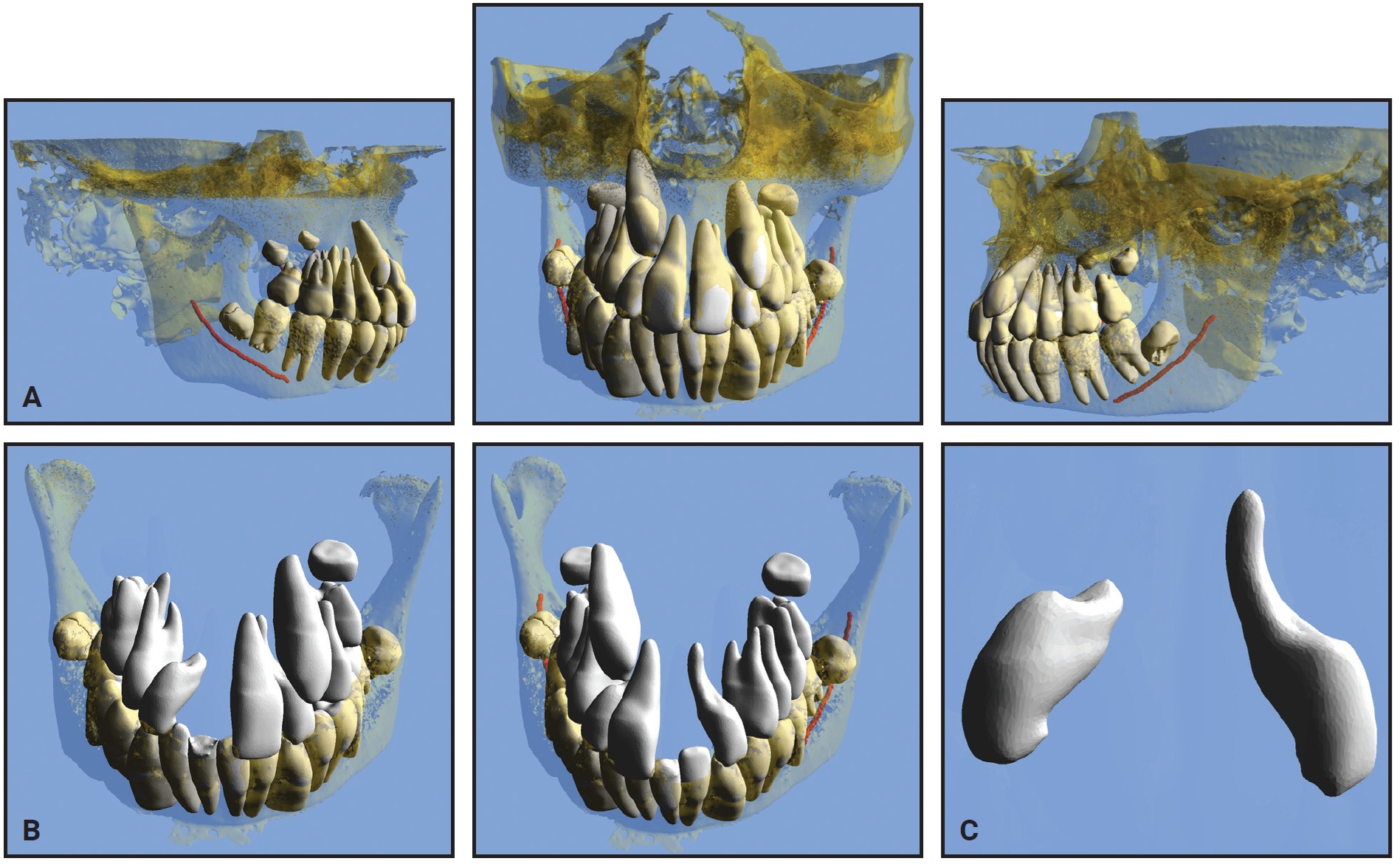
Fig. 2 Case 1. A. Pretreatment three-dimensional views from STL files. B. Views after virtual extraction of adjacent teeth and maxillary bone, showing severe resorption of lateral incisors. C. Upper lateral incisors after all other structures virtually hidden (images courtesy of CephX by Orca Dental AI).
Upon review of the 3D STL interactive models, it was clear that the resorption of the upper lateral incisors was more severe than initially suspected. The treatment plan was therefore revised to include extraction of the two upper lateral incisors and possibly the two lower second premolars (to be determined after the maxillary archform had been established). The extracted lateral incisors showed a similar morphology to those in the STL viewer (Fig. 3).
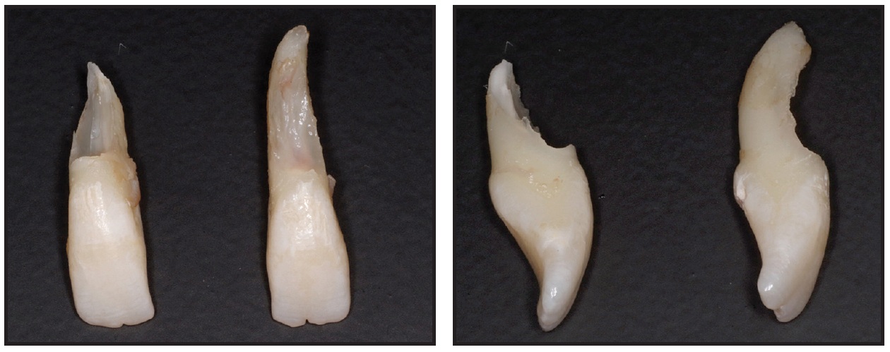
Fig. 3 Case 1. Actual extracted upper lateral incisors.
The STL web viewer of Case 1, which uses the proprietary CephX STL AI algorithm, is available at https://bit.ly/2Yjum5S. (This system is compatible with any smartphone with sufficient memory, but it was taken from a broad field of view and may take close to a minute to download.) To see how the 3D manipulation provides a vastly improved view of the maxillary lateral incisors, select Show/Hide under the View menu on the upper toolbar, then click on any relevant teeth and bony structures to toggle between shown and hidden. Close the Show/Hide menu by clicking Done.
Case 2
A 12-year-old female presented with a submerged lower right second deciduous molar and an impacted permanent lower right second premolar (Fig. 4A).
Fig. 4 Case 2. 12-year-old female patient with Class I skeletal pattern, impacted permanent lower right second premolar, and posterior open bite on right side due to submergence and probable ankylosis of lower right second deciduous molar. Note position of lower right second deciduous molar and lower right second premolar in relation to inferior alveolar nerve and lower border of mandible (continued in next image).
She was referred by a general dentist after complaining of pain in the lower right region, but she had no prior medical history. Clinical evaluation found a Class I skeletal pattern, a dental deviation of the lower midline to the right, and a posterior open bite on the right due to submergence and probable ankylosis of the lower right second deciduous molar. Neither the second decidous molar nor the lower right second premolar was visible clinically.
Radiographic examination revealed the positions of the submerged deciduous molar and the impacted permanent premolar, indicating their proximity to the inferior alveolar nerve canal and the lower border of the mandible, as well as the second premolar’s position relative to the adjacent first molar. A CBCT was requested for further investigation of this anatomical proximity and for surgical access planning (Fig. 4B.
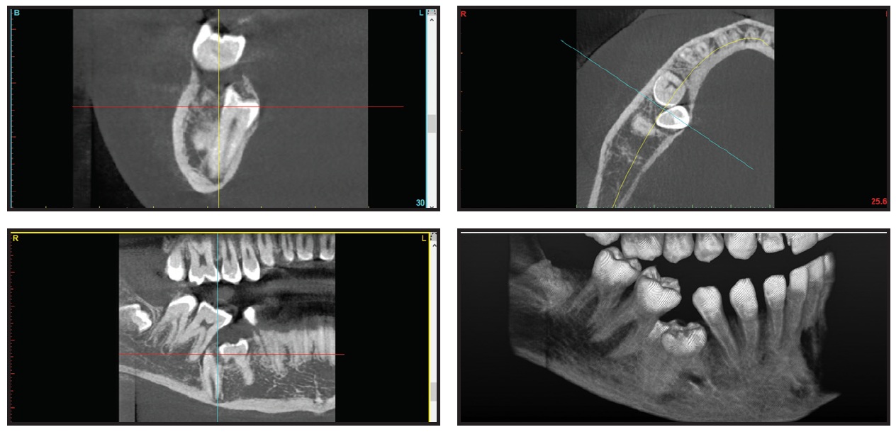
Fig. 4 (cont.) Case 2. 12-year-old female patient with Class I skeletal pattern, impacted permanent lower right second premolar, and posterior open bite on right side due to submergence and probable ankylosis of lower right second deciduous molar. Note position of lower right second deciduous molar and lower right second premolar in relation to inferior alveolar nerve and lower border of mandible.
An STL file was automatically converted from the DICOM file using CephX AI algorithms. The segmented model was virtually manipulated for better depiction of the 3D relationships between the objects (Fig. 5). Considering the proximity of the lower right second deciduous molar to the inferior alveolar nerve and the root of the first molar, it was evident that to avoid damaging those structures, the first vector of force on the lower right second premolar should be lingual and mesial. The STL model also demonstrated a severe mesiolingual rotation of the impacted lower right second premolar, which was not apparent in conventional imaging.
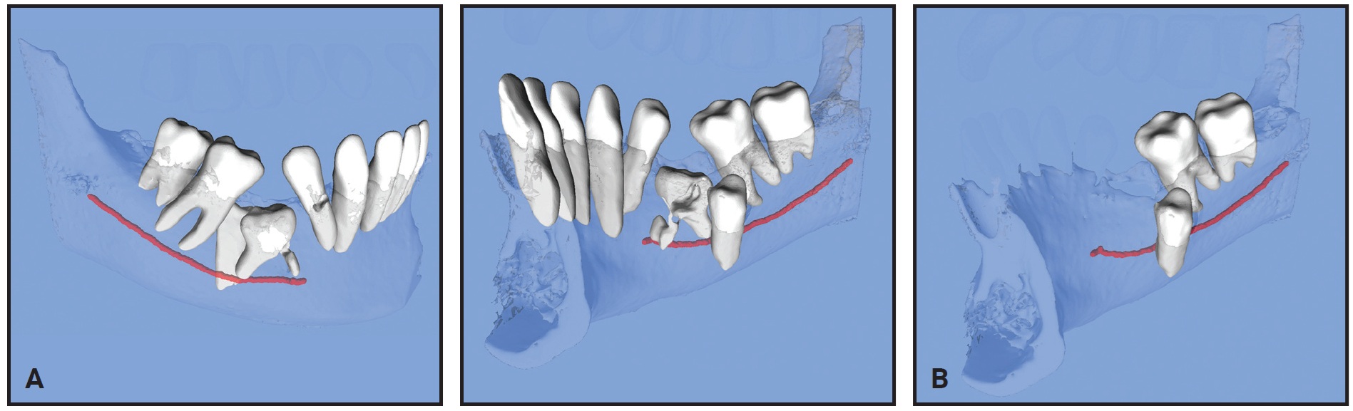
Fig. 5 Case 2. A. Pretreatment 3D views from STL files. B. View after virtual extraction of lower right second deciduous molar and section from lower left lateral incisor through lower right first premolar. Note proximity of inferior alveolar nerve (red) to lower right second premolar root (images courtesy of CephX by Orca Dental AI).
Use the link https://bit.ly/3bHczd8 for 3D manipulation of the STL segmented model with the web viewer, following the same procedure as with Case 1.
Discussion
These cases substantiate the importance of 3D visualization in making an accurate diagnosis. Segmented STL models were instantly converted from standard DICOM data using an AI program.
In the first case, virtual removal of tooth material in the maxillary anterior region revealed severe lateral incisor root resorption that affected our treatment plan, changing it from a nonextraction approach to a two- or four-tooth extraction case. Had we relied solely on axial 2D slices of the CBCT scan, we might have debated whether to extract the maxillary lateral incisors. Impacted canines are often associated with root resorption that progresses rapidly and thus tends to be diagnosed late.15 It has long been acknowledged that 2D radiographs are insufficient for appraisal of the root damage related to ectopic canines,16 mainly because the resorption is commonly located in the middle third of the root (either buccally or palatally), and also because of radiographic superimposition of the adjacent canine.17 Since lateral incisor root resorption can now be easily recognized in CBCT images, it has been found to be even more common than previously assumed, with an estimated prevalence of 48% in cases involving ectopically erupting canines.18 Given the ongoing debate regarding the cost-effectiveness of CBCT scans for orthodontic patients, according to the “as low as reasonably achievable” (ALARA) principle,6,19 the use of CBCT is most commonly recommended for impacted teeth.5,20,21
The second case demonstrates not only the importance of determining the force application vectors in three dimensions, as previously described,8,22 but also the capacity of AI to readily identify the inferior alveolar nerve—an otherwise arduous manual task for a technician. The ability to manipulate the STL model in all directions and view the relationship between the inferior alveolar nerve and a severely impacted premolar is another major advantage of CBCT in cases of mandibular impactions.23 Because orthodontic forces exerting pressure on the inferior alveolar nerve have been reported to cause temporary paresthesia of the lower lip,24,25 an accurate analysis of the relationship between impacted teeth and the inferior alveolar nerve is particularly important.
Conclusion
The orthodontic cases presented in this article demonstrate how technological advances have provided invaluable tools for management of impactions. The combination of CBCT and AI conversion of DICOM files to STL models now enables rotational 3D viewing of the teeth, roots, bones, and mandibular nerves, opening new dimensions in treatment planning. In addition, the ability to hide or virtually extract overlying and obstructing teeth has dramatically improved the orthodontist’s perspective and exposed previously hidden problems.
ACKNOWLEDGMENT: We thank Dr. Nearchos Panayi (past graduate of the Tel Aviv University International Orthodontic Program) for his assistance in obtaining high-quality images of the STL and DICOM files for this article.
FOOTNOTES
- *Registered trademark of Microsoft Corporation, Redmond, WA; www.microsoft.com.
- **Trademark of CephX by Orca Dental AI, Las Vegas, NV; www.cephx.com.
- ***Anatomage, Inc., Santa Clara, CA; www.anatomage.com.
- †Dolphin Imaging and Management Solutions, Chatsworth, CA; www.dolphinimaging.com.
REFERENCES
- 1. Proffit, W.R.; Fields, H.W.; Larson, B.; and Sarver, D.M.: Contemporary Orthodontics, 6th ed., Mosby Elsevier, Philadelphia, 2018.
- 2. Harrell, W.E.; Hatcher, D.C.; and Bolt, R.L.: In search of anatomic truth: 3-dimensional digital modeling and the future of orthodontics, Am. J. Orthod. 122:325-330, 2002.
- 3. Adams, G.L.; Gansky, S.A.; Miller, A.J.; Harrell, W.E.; and Hatcher, D.C.: Comparison between traditional 2-dimensional cephalometry and a 3-dimensional approach on human dry skulls, Am. J. Orthod. 126:397-409, 2004.
- 4. Tsao, D.H.; Kazanoglu, A.; and McCasland, J.P.: Measurability of radiographic images, Am. J. Orthod. 84:212-216, 1983.
- 5. Kapila, S.D. and Nervina, J.M.: CBCT in orthodontics: Assessment of treatment outcomes and indications for its use, Dentomaxillofac. Radiol. 44:1, 2015.
- 6. Silva, M.A.G.; Wolf, U.; Heinicke, F.; Bumann, A.; Visser, H.; and Hirsch, E.: Cone-beam computed tomography for routine orthodontic treatment planning: A radiation dose evaluation, Am. J. Orthod. 133:640.e1-640.e5, 2008.
- 7. Scarfe, W.C.; Li, Z.; Aboelmaaty, W.; Scott, S.A.; and Farman, A.G.: Maxillofacial cone beam computed tomography: Essence, elements and steps to interpretation, Austral. Dent. J. 57:46-60, 2012.
- 8. Harrell, W.E. Jr.: Three-dimensional diagnosis & treatment planning: The use of 3D facial imaging and cone beam CT in orthodontics and dentistry, Austral. Dent. Pract. 7:102-113, 2007.
- 9. Isaacson, K.G.; Thom, A.R.; Atack, N.E.; Horner, K.; and Whaites, E.: Guidelines for the Use of Radiographs in Clinical Orthodontics, 4th ed., British Orthodontic Society, London, 2015, pp. 1-28.
- 10. Huotilainen, E.; Jaanimets, R.; Valášek, J.; Marcián, P.; Salmi, M.; Tuomi, J.; Mäkitie, A.; and Wolff, J.: Inaccuracies in additive manufactured medical skull models caused by the DICOM to STL conversion process, J. Craniomaxillofac. Surg. 42:259-265, 2014.
- 11. Abdelkarim, A. and Jerrold, L.: Clinical considerations and potential liability associated with the use of ionizing radiation in orthodontics, Am. J. Orthod. 154:15-25, 2018.
- 12. Hosny, A.; Parmar, C.; Quackenbush, J.; Schwartz, L.H.; and Aerts, H.J.W.L.: Artificial intelligence in radiology, Nature Rev. Cancer 18:500-510, 2018.
- 13. Orhan, K.; Bayrakdar, I.S.; Ezhov, M.; Kravtsov, A.; and Özyürek, T.: Evaluation of artificial intelligence for detecting periapical pathosis on cone-beam computed tomography scans, Int. Endod. J. 53:680-689, 2020.
- 14. Soffer, S.; Ben-Cohen, A.; Shimon, O.; Amitai, M.M.; Greenspan, H.; and Klang, E.: Convolutional neural networks for radiologic images: A radiologist’s guide, Radiol. 290:590-606, 2019.
- 15. Brin, I.; Becker, A.; and Zilberman, Y.: Resorbed lateral incisors adjacent to impacted canines have normal crown size, Am. J. Orthod. 104:60-66, 1993.
- 16. Ericson, S. and Kurol, J.: Resorption of maxillary lateral incisors caused by ectopic eruption of the canines: A clinical and radiographic analysis of predisposing factors, Am. J. Orthod. 94:503-513, 1988.
- 17. Ericson, S. and Kurol, J.: Radiographic examination of ectopically erupting maxillary canines, Am. J. Orthod. 91:483-492, 1987.
- 18. Ericson, S. and Kurol, J.: Resorption of incisors after ectopic eruption of maxillary canines: A CT study, Angle Orthod. 70:415-423, 2000.
- 19. Abdelkarim, A. and Jerrold, L.: Authors’ response: Readers’ forum, Am. J. Orthod. 154:750-754, 2018.
- 20. Eslami, E.; Barkhordar, H.; Abramovitch, K.; Kim, J.; and Masoud, M.I.: Cone-beam computed tomography vs conventional radiography in visualization of maxillary impacted-canine localization: A systematic review of comparative studies, Am. J. Orthod. 151:248-258, 2016.
- 21. De Grauwe, A.; Ayaz, I.; Shujaat, S.; Dimitrov, S.; Gbadegbegnon, L.; Vannet, B.V.; and Jacobs, R.: A systematic review on justification of CBCT in a paediatric population prior to orthodontic treatment, 41:381-389, 2019.
- 22. Kapila, S.; Conley, R.S.; and Harrell, W.E.: The current status of cone beam computed tomography imaging in orthodontics, Dentomaxillofac. Radiol. 40:24-34, 2011.
- 23. Becker, A.: Orthodontic Treatment of Impacted Teeth, 3rd ed., John Wiley & Sons, Hoboken, NJ, 2012.
- 24. Pithnon, M.M.: Temporary paresthesia of the lower lip during traction of retained inferior premolar, Orthod. Waves 69:171-175, 2010.
- 25. Krogstad, O. and Omland, G.: Temporary paresthesia of the lower lip: A complication of orthodontic treatment. A case report, Br. J. Orthod. 24:13-15, 1997.
-
 DR. LEWIT BOROHOVITZ
 -
 DR. ABRAHAM
 -
 DR. REDMOND
Dr. Lewit Borohovitz is a postgraduate resident and Dr. Abraham is a Clinical Lecturer, International Postgraduate Orthodontic Specialty Program, Department of Orthodontics, Tel Aviv University, Klatzkin 4 St., Tel Aviv, Israel. Dr. Redmond is an Associate Professor, Graduate Orthodontics, Arthur A. Dugoni School of Dentistry, University of the Pacific, San Francisco. Dr. Abraham is on the Advisory Board and Dr. Redmond is on the Industry Experts Committee of CephX by Orca Dental AI; Dr. Lemchen has an interest in the company. E-mail Dr. Abraham at zeevab@gmail.com.