A Modified C-Implant for Simpler and More Efficient Treatment
The original C-orthodontic micro-implant (C-implant*), developed in 2000, gained wide usage because of a unique surface treatment that facilitates partially osseointegrated stability against rotational moments and heavy forces, as well as a removable head with various designs and lengths (Fig. 1A).1,2
The C-implant directly refuted the academic argument that titanium miniscrews should not be osseointegrated. The primary concern was that a screw with a small diameter (1.2-2mm) could easily be fractured. This argument might have applied to miniscrews that were used as simple anchorage for conventional orthodontic treatment. When mini-implants serve not only as skeletal anchorage but also as orthodontic appliances, however, a stronger retention force is required. For that reason, the titanium C-implant was designed with a sandblasted, large-grit, acid-etched (SLA) surface treatment to enable osseointegration as the main means of retention. The partially osseointegrated C-implant could thus serve as an alternative to the conventional large-diameter dental implant in a number of heavy-force applications (Fig. 2). The osseointegration potential of the C-implant has been proven through various animal experiments and clinical studies, and the nanostructure of the screw surface and bone attachment has been evaluated using atom-probe tomography.1,3-6
The C-implant head is available with neck lengths ranging from 1mm to 3mm, allowing for various traction applications. The .8mm-diameter hole can accommodate an orthodontic wire if needed. The longest screw (10.5mm) can also be used as a provisional implant for a congenitally missing anterior tooth.
The C-implant has three main design features to resist fracture. First, the modified cylindrical body promotes even stress distribution during insertion; since the pitch of the screw is less sharp than that of other mini-implants, it also avoids stress concentration during removal, even if it has become osseointegrated. Second, to compensate for this feature, the screw is self-tapping (after a pilot hole is drilled) instead of self-drilling. Third, the two-piece design, with the head and screw as separate parts, makes it possible to reduce stress on the neck during placement and removal. In a 2008 clinical study, while the average removal torque was 16.4Ncm, the C-implant was removed without fracture even with forces as high as 35.4Ncm.7
Similar articles from the archive:
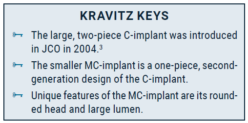
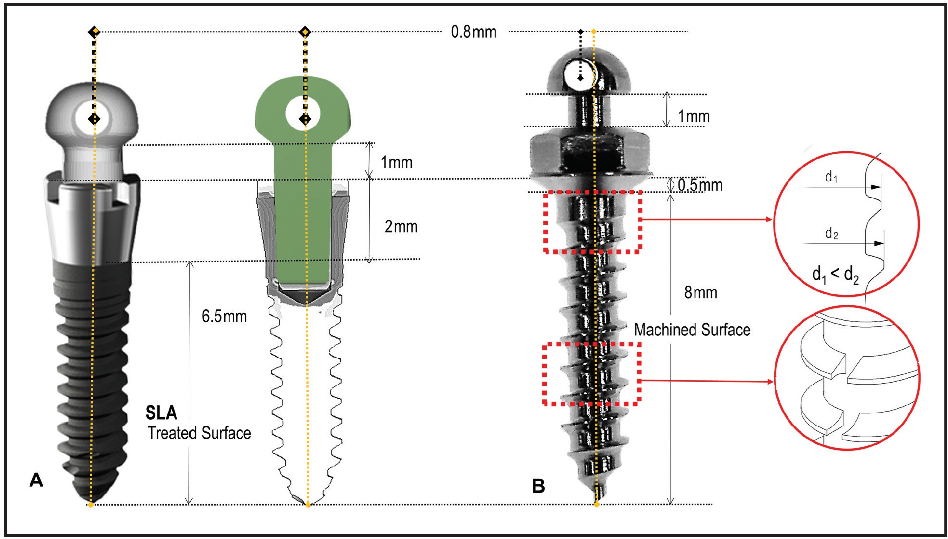
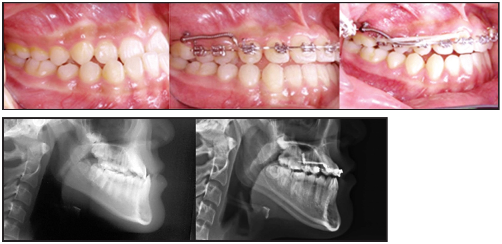
Fig. 2 Two 1.8mm × 8.5mm C-implants used for total protraction of upper dentition to correct anterior crossbite with pushing technique.
Compared with conventional orthodontic miniscrews, however, C-implants are more complicated to insert and remove. Pilot drilling is required for each screw, and additional procedures are required to separate and fit the heads. Additionally, the screw is relatively large: 1.8mm in diameter, increasing to 2mm in the cervical area and 2.5mm at the head. Although it is possible to apply orthodontic force immediately after implantation, the normal healing period for osseointegration is four weeks, which may lengthen treatment. Finally, the device is comparatively expensive because it requires the same manufacturing process and surface treatment as a dental implant. The offsetting benefit is its remarkable stability.5
MC-Implant
To overcome these drawbacks while taking advantage of the best characteristics of conventional miniscrews, we developed a second-generation device called the modified C-implant (MC-implant**). Made of titanium grade 5 alloy, it has a one-piece design, combining the head with the screw body. The MC-implant is 1.6mm in diameter—the same as a standard miniscrew—and is self-drilling. It is available in three lengths (6mm, 8mm, and 10mm), but the 8mm MC-implant is the most used.4,8 Its entire length, including the 1mm neck and the contact point with soft tissue, is 8.5mm, the same as that of the C-implant3,5,6 (Fig. 1B). Clinical experience with the MC-implant’s rounded head design has found less tissue irritation for the patient than with conventional miniscrews.
The main advantage of the C-implant is that its surface treatment facilitates osseointegration. With the MC-implant, the smaller upper spirals of the screw allow more bone to fill in and integrate with the uppermost spirals during the bone-healing process. Small notches cut into the lower spirals can further increase bone attachment during healing and thus provide more resistance to rotational forces.9,10
The hole in the MC-implant head is .8mm in diameter—the same as that of the C-implant, but .1mm larger than those of other miniscrews. The hole is slightly offset from the long axis of the screw to minimize the risk of loosening if a wire is inserted into the MC-implant and a counterclockwise rotation force is applied (Fig. 3).7 This eccentric position also avoids the tendency of an applied force to unscrew the implant, since the long axes of the screw and the hole are not coincident. Although finite element analysis has confirmed the rotational resistance of this screw and head-hole design, the actual clinical effects will need further study.
Case Report
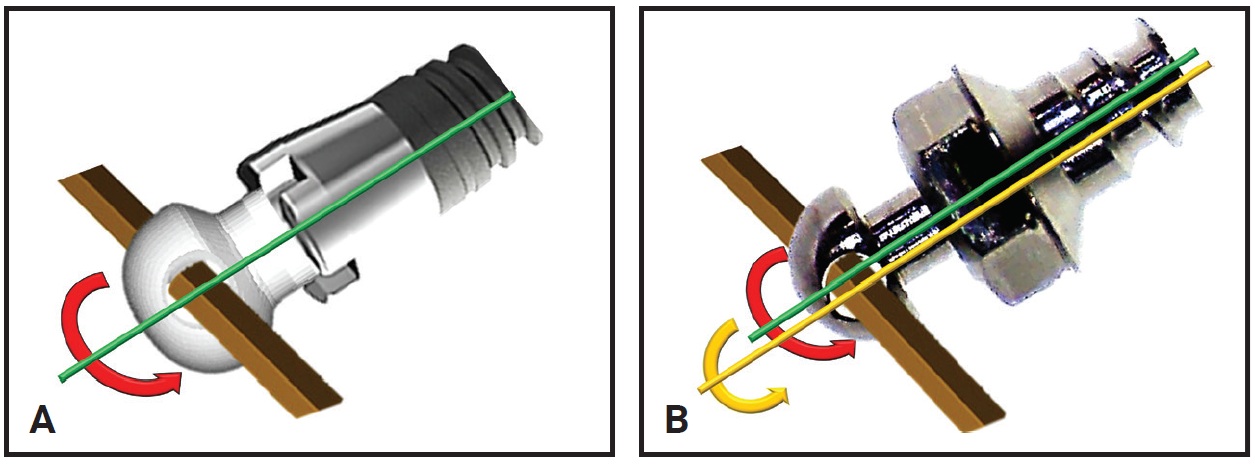
Fig. 3 A. Wire passing through .8mm-diameter hole in C-implant head generates rotational axis coincident with screw axis. B. Eccentric hole position in MC-implant creates discrepancy between screw axis and generated rotational axis and prevents loosening when counterclockwise rotation force is applied.
A 13-year-old female presented with an anterior deep bite, congenitally missing lower permanent central incisors and second premolars, and a skeletal Class II relationship (Fig. 4). We planned to use nonextraction treatment to correct the skeletal discrepancy.
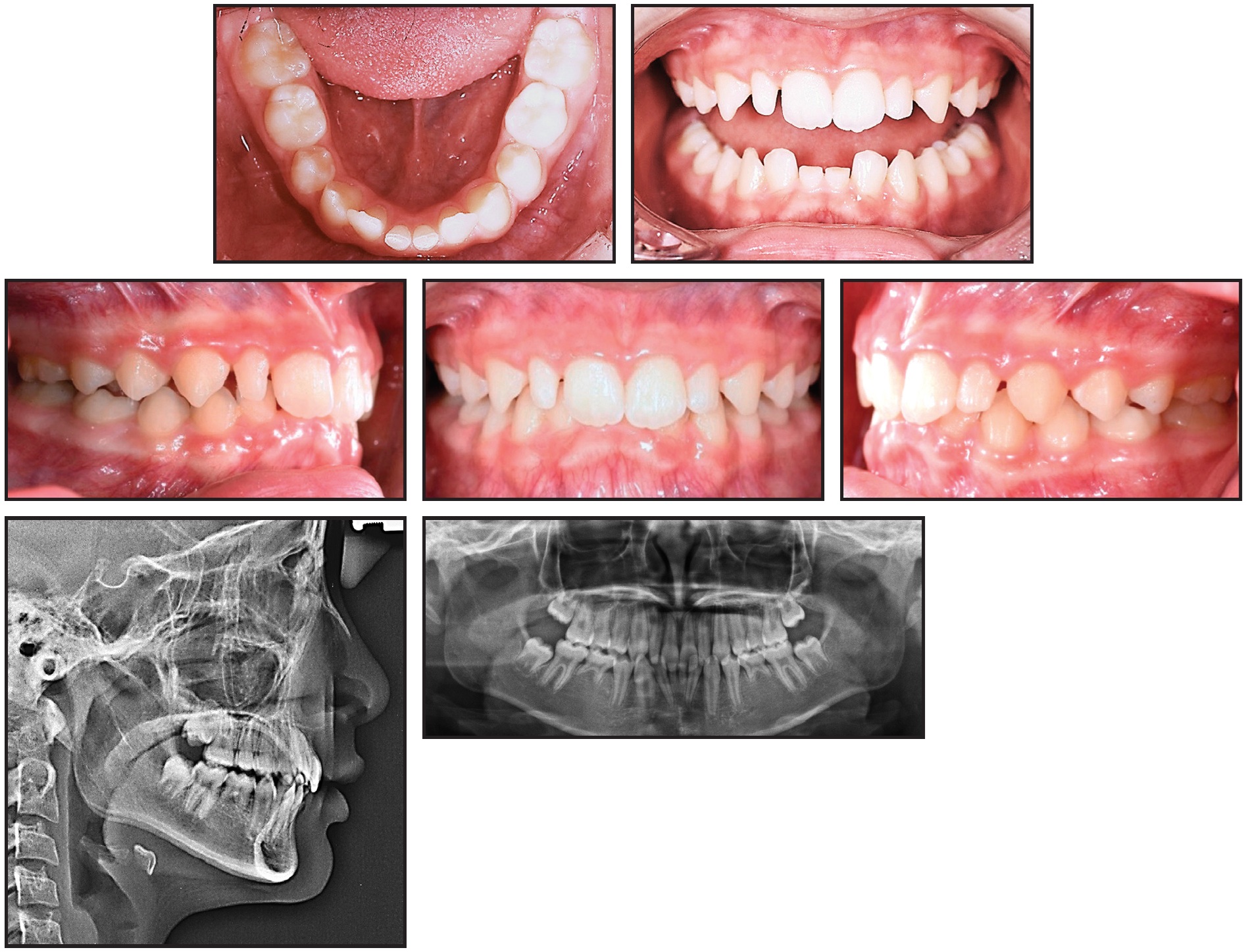
Fig. 4 13-year-old female patient with anterior deep bite, congenitally missing lower permanent central incisors and second premolars, and skeletal Class II relationship before treatment.
Both arches were bonded with .022" Tweemac-prescription Quicklear*** brackets. After 24 months of orthodontic treatment, the overjet and overbite were corrected, and Class I canine and molar relationships were achieved (Fig. 5).
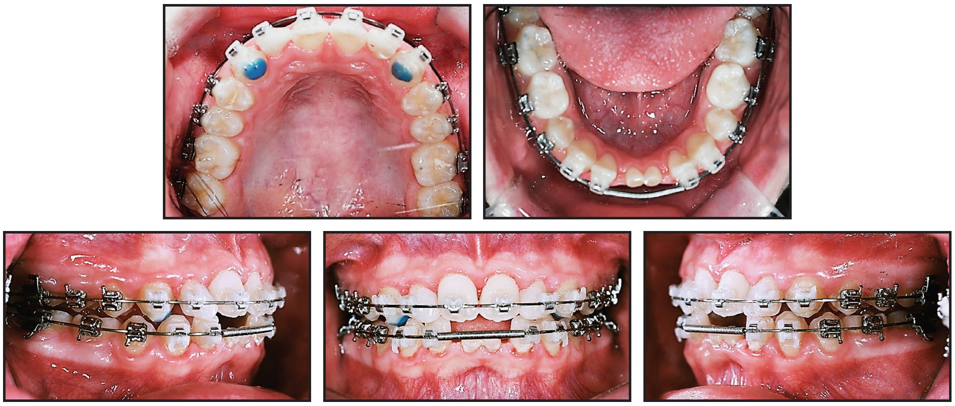
Fig. 5 After 24 months of treatment with .022" Tweemac-prescription Quicklear*** brackets, anterior deep bite corrected and space gained for restoration of lower central incisors.
Because of the severe external resorption of the deciduous lower central incisors, we prescribed provisional implant restorations using 1.6mm × 8mm MC-implants.2,11 Instead of a flap operation, considering the loss of anterior alveolar bone, we planned for immediate insertion of the MC-implants following extraction of the deciduous incisors. After infiltration of anesthesia, each deciduous incisor was extracted with forceps, and an MC-implant was inserted in the extraction socket at an angle following the long axis of the extracted tooth (Fig. 6).
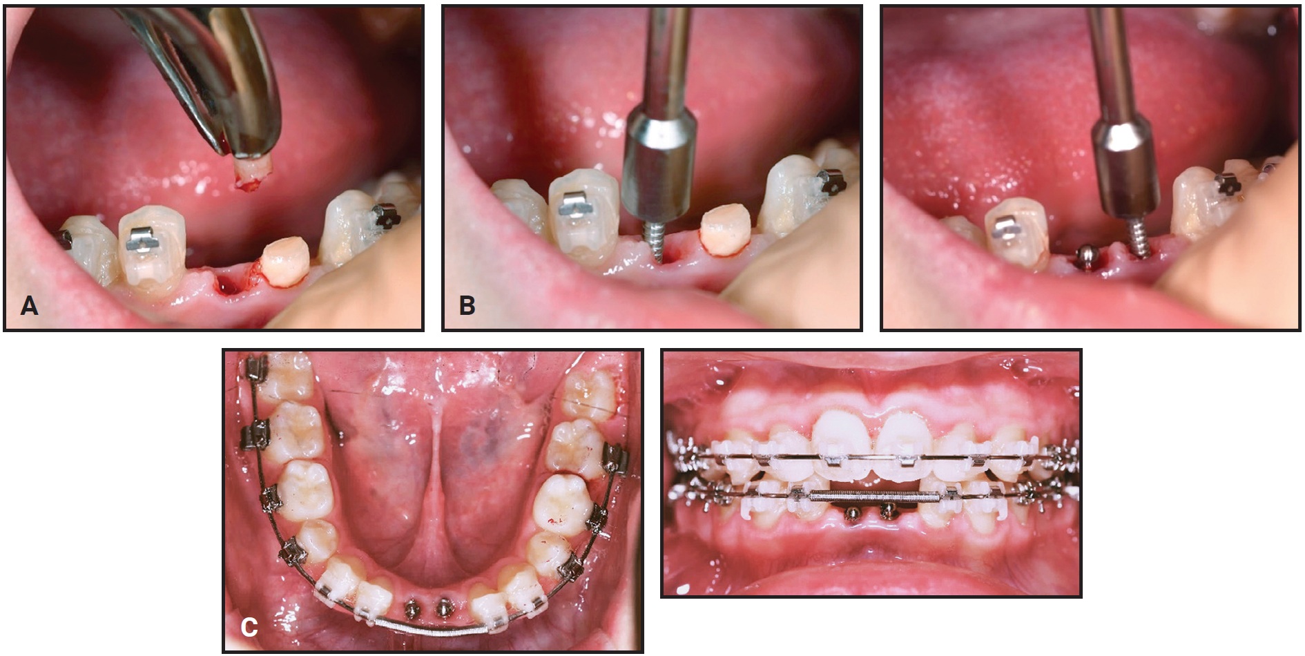
Fig. 6 After 26 months of treatment, 1.6mm × 8mm MC-implants inserted as provisional dental implants. A. Resorbed and shortened root observed after extraction of deciduous lower right central incisor. B. MC-implants placed in extraction sockets, following original long axes of teeth. C. MC-implants in position.
The stability of the MC-implants was confirmed radiographically after insertion (Fig. 7).
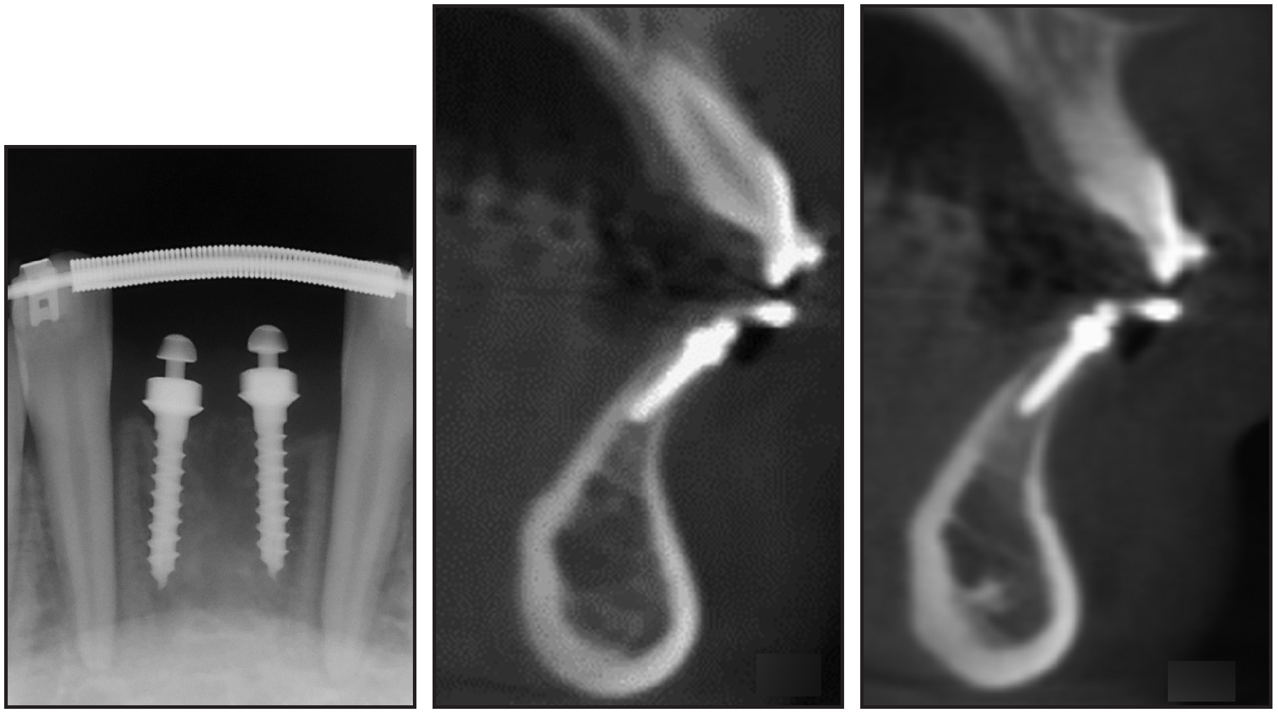
Fig. 7 MC-implants at center of alveolar bone housing, parallel to adjacent lateral incisors.
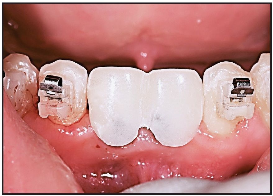
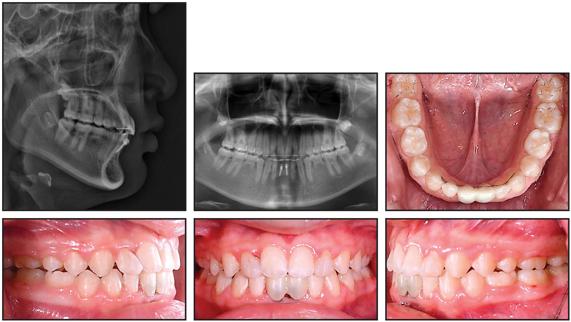
Fig. 9 Patient after 29 months of treatment.
One year later, the patient exhibited a stable occlusion with Class I canine and molar relationships and favorable jaw growth (Fig. 10).
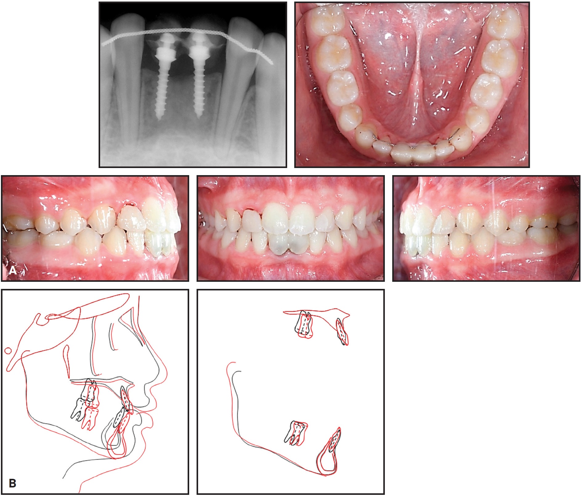
Fig. 10 A. Patient one year after treatment. B. Superimposition of pretreatment and seven-months-post-treatment cephalometric tracings.
Discussion
Lack of mini-implant stability can be a serious problem during orthodontic treatment, causing delays and even bone loss.12,13 The SLA-treated titanium mini-implant has proved to be more stable than machined-surface mini-implants, thanks to its capacity for partial osseointegration.6,14,15 Kim and colleagues used atomic-force microscopy to demonstrate an increased space for bone attachment in the microstructure and rough macrostructure produced by the surface treatment of the C-implant, resulting in its enhanced stability.16 The versatile, two-piece C-implant can anchor challenging orthodontic movements such as en masse retraction of anterior teeth, distalization of posterior teeth, and intrusion of posterior teeth.14 It can also be used for maxillomandibular fixation after orthognathic surgery17 or as a provisional implant.2
Although the C-implant has many advantages as a partially osseointegrated mini-implant, there are some weaknesses in its design. A conventional orthodontic miniscrew is a narrower 1.6mm in diameter, with a one-piece design and a hexagonal driver adaptation, and is self-drilling for easy insertion and removal. The MC-implant was developed to incorporate these useful features while retaining the multidirectional force resistance of the C-implant. Its stability is attributable to the offset hole in the screw head and to the notches in the screw spirals.10,18 Inclined insertion is recommended to increase resistance to unscrewing forces and to avoid damage to the adjacent roots.
The MC-implant can be used for the same treatment applications as the C-implant. For anterior retraction, an archwire can slide with minimal friction through the .8mm hole, eliminating the need for posterior fixed appliances. Anterior torque is easily achieved by adding gable bends to an .016" × .022" or .017" × .025" stainless steel archwire.19,20 Resistance to rotational moments permits many more biomechanical applications. In the case shown here, the MC-implant was used as a provisional crown-supporting implant for congenitally missing lower incisors in a young patient.2 Heavy lateral or occlusal forces should be avoided in such cases; the main purposes of the provisional implants are space maintenance, prevention of alveolar bone loss, and improvement of esthetics until growth is complete.
Finite element analysis and in vivo debonding-strength tests of MC-implants with various configurations are needed to assess the degree of structural osseointegration that can be achieved in comparison with the C-implant.
FOOTNOTES
- *Cimplant Co., Seoul, South Korea; www.cimplant.com.
- **Bio-Action screw, Jin Biomed Co., Gyeonggi, South Korea; www.jbmed.co.kr.
- ***Registered trademark of Forestadent GmbH, Pforzheim, Germany; www.forestadent.com.
REFERENCES
- 1. Chung, K.R.: C-Implant, in Text Book of Speedy Orthodontics, ed. K.R. Chung, Jeesung, Seoul, South Korea, 2001, pp. 99-113.
- 2. Jeong, D.M.; Choi, B.; Choo, H.; Kim, J.H.; Chung, K.R.; and Kim, S.H.: Novel application of the 2-piece orthodontic C-implant for temporary crown restoration after orthodontic treatment, Am. J. Orthod. 140:569-579, 2011.
- 3. Chung, K.R.; Kim, S.H.; and Kook, Y.A.: The C-orthodontic micro-implant, J. Clin. Orthod. 38:478-486, 2004.
- 4. Cha, J.Y.; Kil, J.K.; Yoon, T.M.; and Hwang, C.J.: Miniscrew stability evaluated with computerized tomography scanning, Am. J. Orthod. 137:73-79, 2010.
- 5. Lee, S.J.; Ahn, S.J.; Lee, J.W.; Kim, S.H.; and Kim, T.W.: Survival analysis of orthodontic mini-implants, Am. J. Orthod. 137:194-199, 2010.
- 6. Kim, S.H.; Chung, K.R.; and Nelson, G.: The Biocreative strategy, Part 1: Foundations, J. Clin. Orthod. 52:258-274, 2018.
- 7. Kim, S.H.; Cho, J.H.; Chung, K.R.; Kook, Y.A.; and Nelson, G.: Removal torque values of surface-treated mini-implants after loading, Am. J. Orthod. 134:36-43, 2008.
- 8. Song, Y.Y.; Cha, J.Y.; and Hwang, C.J.: Mechanical characteristics of various orthodontic mini-screws in relation to artificial cortical bone thickness, Angle Orthod. 77:979-985, 2007.
- 9. Wu, S.W.; Lee, C.C.; Fu, P.Y.; and Lin, S.C.: The effects of flute shape and thread profile on the insertion torque and primary stability of dental implants, Med. Eng. Phys. 34:797-805, 2012.
- 10. Choi, J.Y.; Kim, M.J.; Kim, S.H.; Chung, K.R.; and Nelson, G.: Effect of different head hole position on the rotational resistance and stability of orthodontic miniscrews: A three-dimensional finite element study, Sensors 21:3798, 2021.
- 11. Paek, J.; Ahn, H.W.; Jeong, D.M.; Shim, J.S.; Kim, S.H.; and Chung, K.R.: Application of the 2-piece orthodontic C-implant for provisional restoration with laser welded customized coping: A case report, Head Face Med. 11:7, 2015.
- 12. Costa, A.; Raffaini, M.; and Melsen, B.: Microscrews as orthodontic anchorage: A preliminary report, Int. J. Adult Orthod. Orthog. Surg. 13:201-209, 1998.
- 13. Oh, H.J.; Cha, J.Y.; Yu, H.S.; and Hwang, C.J.: Histomorphometric evaluation of the bone surrounding orthodontic miniscrews according to their adjacent root proximity, Kor. J. Orthod. 48:283-291, 2018.
- 14. Kim, S.H.; Choi, J.H.; Chung, K.R.; and Nelson, G.: Do sand blasted with large grit and acid etched surface treated mini-implants remain stationary under orthodontic forces? Angle Orthod. 82:304-312, 2012.
- 15. Brånemark, P.I.: Osseointegration and its experimental background, J. Prosth. Dent. 50:399-410, 1983.
- 16. Kim, J.S.; Ahn, J.P.; Kim, Y.H.; Seo, K.W.; Zadeh, H.; and Kim, S.H.: Atomic layout of an orthodontic titanium mini-implant in human tissue: Insights into the possible mechanisms during osseointegration, Angle Orthod. 89:292-298, 2019.
- 17. Kim, S.H.; Kook, Y.A.; Lee, W.; Kim, I.; and Chung, K.R.: Two-component mini-implant as an efficient tool for orthognathic patients, Am. J. Orthod. 135:110-117, 2009.
- 18. Choi, J. Y.; Cho, J.; Oh, S.H.; Kim, S.H.; Chung, K.R.; and Nelson, G.: Effect of different surface designs on the rotational resistance and stability of orthodontic miniscrews: A three-dimensional finite element study, Sensors 21:1964, 2021.
- 19. Mo, S.S.; Kim, S.H.; Sung, S.J.; Chung, K.R.; Chun, Y.S.; Kook, Y.A.; and Nelson, G.: Factors controlling anterior torque during C-implant-dependent en-masse retraction without posterior appliances, Am. J. Orthod. 140:72-80, 2011.
- 20. Mo, S.S.; Noh, M.K.; Kim, S.H.; Chung, K.R.; and Nelson, G.: Finite element study of controlling factors of anterior intrusion and torque during Temporary Skeletal Anchorage Device (TSAD) dependent en masse retraction without posterior appliances: Biocreative hybrid retractor (CH-retractor), Angle Orthod. 90:255-262, 2020.
-
 DR. KIM
 -
 DR. CHOI
 -
 DR. CHUNG
 -
 DR. NELSON
Dr. Kim is a Contributing Editor of the Journal of Clinical Orthodontics and a Professor and Head of Department, Dr. Choi is a Clinical Assistant Professor, and Drs. Chung and Nelson are Clinical Adjunct Professors, Department of Orthodontics, Graduate School, Kyung Hee University, #23 Kyungheedaero, Dongdaemun-gu, Seoul 02447, South Korea. E-mail Dr. Kim at bravortho@khu.ac.kr.