CAD/CAM Software for Three-Dimensional Printing
A digital model requires preparation prior to three-dimensional printing. After removing excess data, the operator must repair any holes, adjust the height of the base, hollow out the interior, and imprint a patient identifier (Fig. 1). Because the software supplied with the 3D printer may be unable to perform all these manipulations, other computer-aided design and manufacturing (CAD/CAM) software programs are required.
Previous articles have described the application of intraoral scanners1 and 3D printers2 in orthodontic practice. This third installment covers the CAD/CAM software needed for digital model preparation. We will review the steps used to convert a raw, exported STL file to a processed digital model ready for 3D printing (Fig. 2).
Similar articles from the archive:
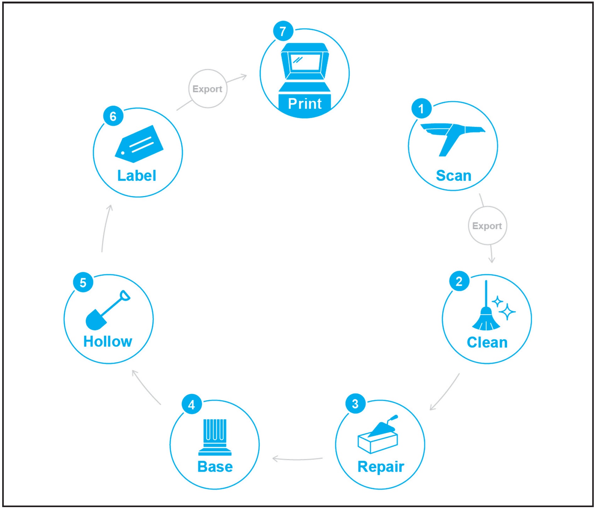
Fig. 1 Hardware and software steps required to prepare STL file for three-dimensional printing. STL file created from intraoral scan; exported to computer; cleaned, repaired, and prepared using CAD/CAM software; and exported to 3D printer.
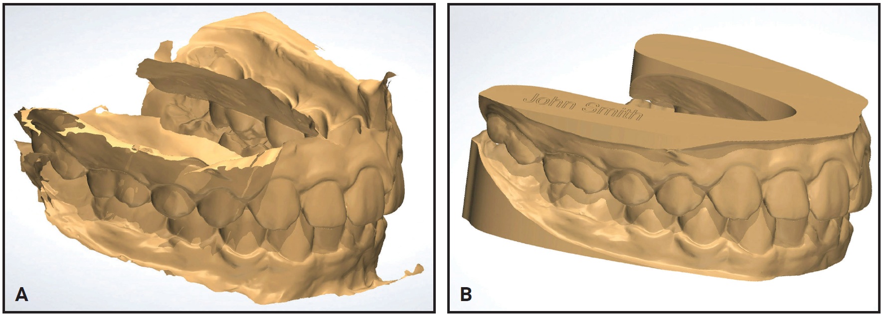
Fig. 2 A. Raw STL file created from intraoral scan. B. Cleaned and repaired digital model ready for 3D printing.
Understanding STL
STL is a file format developed in 1987 by Charles Hall to support his stereolithographic 3D printer. Its file extension, STL, is believed to be either an abbreviation of the word “stereolithography” or an acronym for Standard Tessellation Language or Standard Triangulation Language. The STL file made it possible to transfer a 3D model from a computer screen to a 3D printer. Even after 30 years of usage, STL remains the most commonly used file type for intraoral scanners.
STL describes a 3D model’s surface by using an array of linked triangles to recreate the surface geometry. This triangulation of a surface causes the faceting of the 3D model. Although newer file types can provide more detailed data, the main benefit of STL is its simplicity. STL is based on open-source code and is freely available, meaning anyone may inspect, enhance, or share an STL file. Its universal format enables STL to work with nearly every CAD software program and 3D printer. Moreover, its vector-based (triangle) graphics provide scalability without any loss of resolution. The STL file is perhaps the single most important item in the 3D printing workflow.
The simplicity of STL does create some drawbacks. The file format describes only surface geometry, so there is no representation of color; items can be printed in just a single color. In addition, STL does not provide copyright information, file security, or the ability to detect errors in the surface mesh.
Cleaning and Repairing the Mesh
“Mesh” is a term used to describe the surface of a 3D model. The mesh’s smoothness increases as the number of surface triangles increases (Fig. 3).
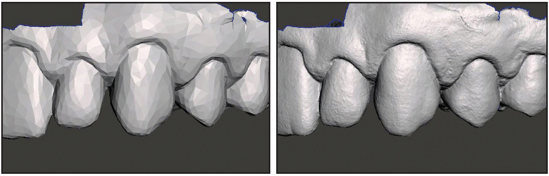
Fig. 3 Mesh becomes smoother as number of triangles and file size increase.
A typical digital model’s mesh comprises hundreds of thousands of triangles, some of which will need to be removed or repaired following a scan. Therefore, the first modification of the STL file is to clean and repair its mesh.
Cleaning the mesh involves the elimination of extraneous or redundant (duplicated) surface structures, like using a Buffalo knife to scratch away excess artifacts from a stone model. The software allows the operator to isolate a specific region or select a filter to automatically clean the entire digital model (Fig. 4). This process includes a step called “mesh decimation.” Some scanners produce STL files with extraordinarily large numbers of surface triangles. Decimating a scan reduces the number of triangles, which reduces the STL file size. For example, a digital model with 200,000 surface triangles can be decimated to 100,000 without any impactful loss of detail. The difference in surface texture would not be visible to the naked eye, nor would it be noticed in the output of a 3D printer.
Repairing the mesh involves using the same software program to fill small voids and reorient inverted triangles—those that are flipped so the inner surface faces out (Fig. 5). These “inverted normals” prevent the printer from distinguishing between the inside and outside of the model. Repairing the mesh is analogous to patching up voids in a stone model with block-out resin. A completely closed mesh without any voids is said to be “watertight.”
Base Modification, Hollowing, and Labeling
The next modification of the STL file is the creation of a flat surface base. Like an alginate impression, an intraoral digital scan has no base. The base is built by stretching the model’s gingiva vertically and sectioning across it to create a flat surface that can rest on the print bed (Fig. 6). Alternatively, a specific base shape such as the one required by the ABO can be added.
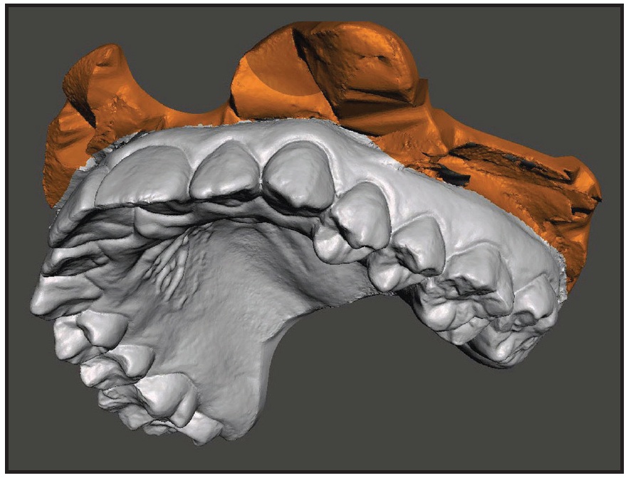
Fig. 4 Extraneous material selected for removal during cleaning.
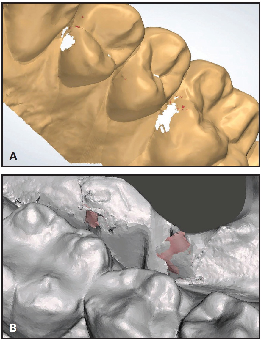
Fig. 5 Voids (A) and inverted normals (B) in mesh.
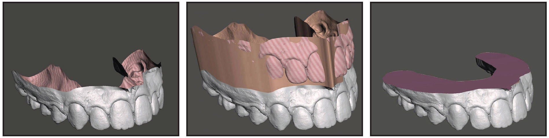
Fig. 6 Stretching gingiva and sectioning across to create flat surface for building model base.
After base modification, the next step is to hollow the inside of the digital model. Hollowing removes all internal filler, leaving only a shell for support (Fig. 7). This lessens the amount of print material, thus reducing model expenses and, potentially, printing time. Wall thickness depends on the model’s demands. For example, a digital model used to make a thermoformed appliance requires thicker walls than a study model used only for diagnostics. To simplify the STL preparation process, all digital models are usually set to the wall thickness needed for the most demanding task.
The final step prior to 3D printing is to label the digital model. This is essential because multiple models from different patients may be printed simultaneously on each bed. Labeling can be as simple as creating a text box and dragging it to the desired location (Fig. 8). Custom text is embossed or engraved at the chosen size and depth (typically .5mm).
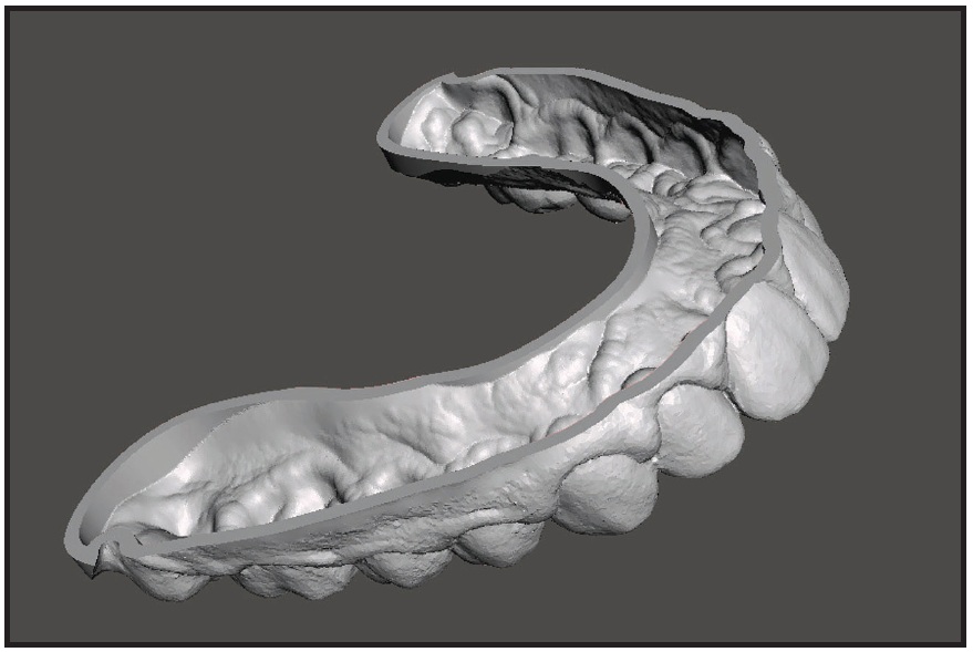
Fig. 7 Hollowed digital model requires less print material (base removed for visual clarity).
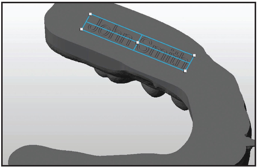
Fig. 8 Labeling model with patient identifier.
Software Products
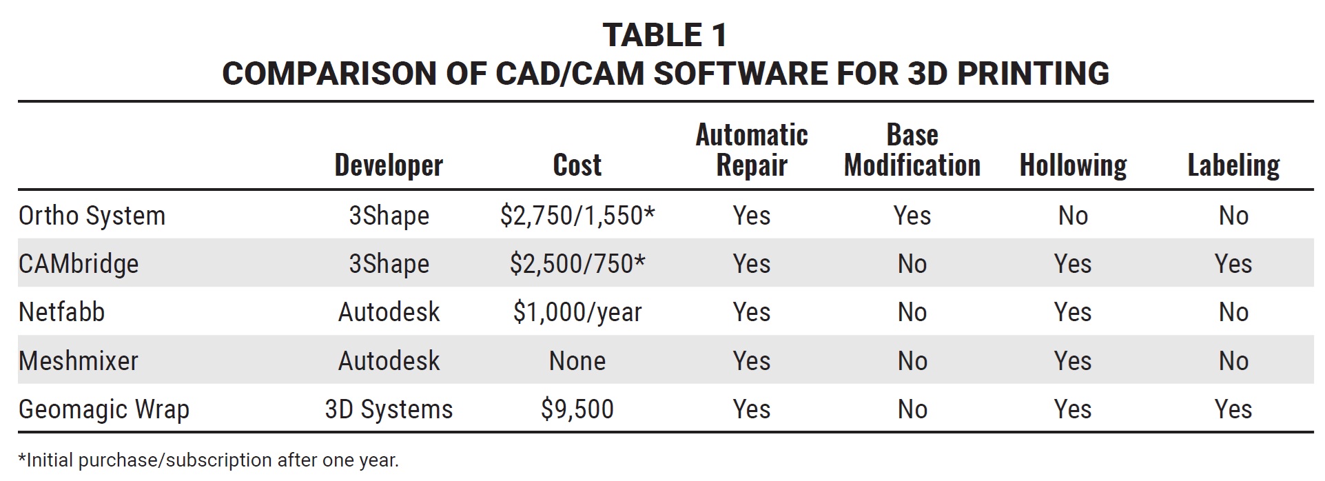
Table 1 lists some popular third-party CAD/CAM software programs for cleaning, repairing, and modifying digital models. Some of these products are free; others require paid subscriptions that typically cost a few thousand dollars annually, adding to the overall expense of 3D printing.
Trios* Ortho System** provides a variety of modules to import, prepare, and export scans for printing: Ortho Planner,** OrthoAnalyzer,** and Study Model Builder.** Digital models are cleaned and repaired simultaneously for maximum efficiency. The 3Shape hardware is not required to use Ortho System, but a proprietary software program, CAMbridge,* is needed for the final steps of hollowing and labeling.
CAMbridge works with any of the 3Shape software products and serves as the link between digital model design and manufacturing (thus its name, “CAM-bridge”). This software program automates hollowing and labeling, meaning it allows batch processing of multiple models at a time. It also arranges the digital models on the print bed for optimal spacing. Although CAMbridge is currently available only for select 3D printers, the combination of Ortho System and CAMbridge software results in a fully digital solution from scan to 3D print.
Meshmixer,*** a freeware program from Autodesk offers a wide range of capabilities, from simple plane cuts to complex mesh manipulations like hollowing.
To label the digital model, Meshmixer needs a separate program, most commonly Windows 3D Builder.† Currently included in all versions of Windows 10, this user-friendly application provides functions for plane cutting, base extrusion, and labeling.
Netfabb‡ is a paid subscription-based program offered by Autodesk. Premium and Ultimate versions are available, but the Standard version allows both mesh manipulation and labeling and is therefore adequate for orthodontic use. Although changes in the mesh area can be automated, labeling is still performed manually prior to export.
Geomagic offers a variety of software programs for advanced CAD/CAM operations, including Geomagic Design,†† Geomagic Freeform,‡‡ Geomagic Sculpt,†† and Geomagic Wrap.‡‡ The sophistication of these products makes them more costly than necessary for digital orthodontic models.
Direct Appliance Printing
Any orthodontic appliance can be designed with a CAD software program, but virtually all of them currently need to be made indirectly from 3D-printed models. The only directly printed dental appliance now available is a biteguard made with an EnvisionTEC§ printer. The CEREC§§ system, by contrast, involves a form of milling or subtractive manufacturing. As printing technology and materials improve, however, orthodontists will soon be able to design and fabricate brackets, auxiliaries, expanders, retainers, and aligners directly from a 3D printer, without the need for physical models.
Conclusion
The process of 3D printing is not as simple as pushing the print button. An STL file must first be created from an intraoral scan and then exported to a computer, where it is prepared using CAD/CAM software. The software is required to clean and repair the STL, thus creating a watertight digital model ready for fabrication in a 3D printer. Understanding CAD/CAM software is essential for 3D printing, and ultimately for building your in-office digital print lab.
FOOTNOTES
- *Registered trademark of 3Shape, Copenhagen, Denmark; www.3shape.com.
- **Trademark of 3Shape, Copenhagen, Denmark; www.3shape.com.
- ***Autodesk, Inc., San Rafael, CA; www.autodesk.com.
- †Copyright Microsoft Corporation, Redmond, WA; www.microsoft.com.
- ‡Registered trademark of Autodesk, Inc., San Rafael, CA; www.autodesk.com.
- ††Trademark of 3D Systems, Inc., Rock Hill, SC; www.3Dsystems.com.
- ‡‡Registered trademark of 3D Systems, Inc., Rock Hill, SC; www.3Dsystems.com.
- §EnvisionTEC, Inc., Dearborn, MI; www.envisiontec.com.
- §§Registered trademark of Sirona Dental, Inc., Charlotte, NC; www.cereconline.com.
REFERENCES
- 1. Kravitz, N.D.; Groth, C.; Jones, P.E.; Graham, J.W.; and Redmond, W.R.: Intraoral digital scanners, J. Clin. Orthod. 48:337-347, 2014.
- 2. Groth, C.; Kravitz, N.D.; Jones, P.E.; Graham, J.W.; and Redmond, W.R.: Three-dimensional printing technology, J. Clin. Orthod. 48:475-485, 2014.
-
 DR. KRAVITZ
 -
 DR. GROTH
 -
 DR. SHANNON
Dr. Kravitz is an Associate Editor of the Journal of Clinical Orthodontics and in the private practice of orthodontics at 25055 Riding Plaza, Suite 110, South Riding, VA 20152; e-mail: nealkravitz@gmail.com. Dr. Groth is in the private practice of orthodontics in Birmingham, MI, and is co-founder of Motor City Lab Works, an orthodontic three-dimensional printing lab. Dr. Shannon is in the private practice of orthodontics in Grandville, MI.