Generating an Ideal Virtual Setup with Three-Dimensional Crowns and Roots
The goal of orthodontic treatment is to move teeth from malocclusion to a functional, esthetic, and stable ideal occlusion in which all dental crowns and roots are in the correct three-dimensional positions. Mesiodistal, labiolingual, and occlusogingival positions and axial rotations can be determined solely from the crowns of the teeth, but mesiodistal angulations and faciolingual inclinations may be better assessed by viewing both the crowns and roots.1-4 Although most of the focus in orthodontic treatment is on crown positions as determinants of esthetic appearance and occlusal contacts, improper root positions may increase the risk of relapse, periodontal damage, and undesirable tooth movements under occlusal loads.5-7
To check root alignment, 67% and 80% of U.S. orthodontists take progress and post-treatment panoramic x-rays, respectively.8 Studies have shown, however, that panoramic x-rays are imprecise as a means of identifying problems with tooth angulation.9-12 Recent advances in 3D technology and software have provided diagnostic tools for more accurate measurement of mesiodistal angulation and faciolingual inclination.13,14 Still, many of the digital systems used to fabricate customized orthodontic appliances - including Invisalign*, Incognito**, and Insignia***15-18 - do not display the roots in their virtual setups.
Similar articles from the archive:
A recently reported technique has the capability of monitoring root positions at any stage of orthodontic treatment by combining a cone-beam computed tomography (CBCT) scan with either an intraoral or extraoral digital scan of the crowns.19,20 The present article describes the use of this process to evaluate and modify crown and root positions for construction of an ideal 3D setup.
Procedure
The procedure is illustrated in a 32-year-old female who presented with a skeletal and dental Class I malocclusion (Fig. 1).
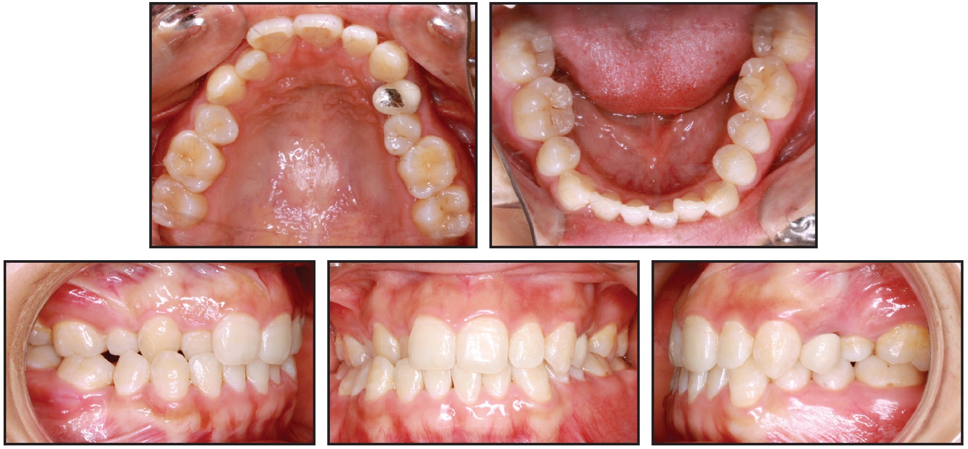
Fig. 1 32-year-old female Class I patient with missing upper right first and lower right second premolars before treatment.
Casts were poured with orthodontic stone from polyvinyl siloxane impressions. After a pretreatment CBCT was performed with a Sironas Galileos Comfort† 3D scanner, the images were reconstructed with a .25mm slice thickness and exported as Digital Imaging and Communications in Medicine (DICOM) files.21
The DICOM files were imported into Mimics 17.0‡ software. Threshold segmentation of all three views (sagittal, coronal, and transverse) was performed on each individual tooth to create 3D virtual models. An initial threshold of 2.224-4.095 gray levels was manually adjusted to minimize the surrounding bone while accurately capturing all the teeth. After region growing, cropping, and 3D mask editing were performed with the Mimics 17.0 software, smoothing and wrapping functions were used to optimize the virtual models. The CBCT teeth were imported into 3-matic 9.0‡ software, which has the capability to perform surface-based superimposition of 3D models.
The physical casts were sectioned and rebuilt into an initial, tentative setup, which was then scanned with an Ortho Insight†† extraoral laser scanner, exported as a stereolithography (STL) file, and imported into the 3-matic 9.0 program. The 3D position of the roots was generated by superimposing the crown of each individually segmented CBCT tooth onto the corresponding crown of the laser-scanned initial setup (Fig. 2).
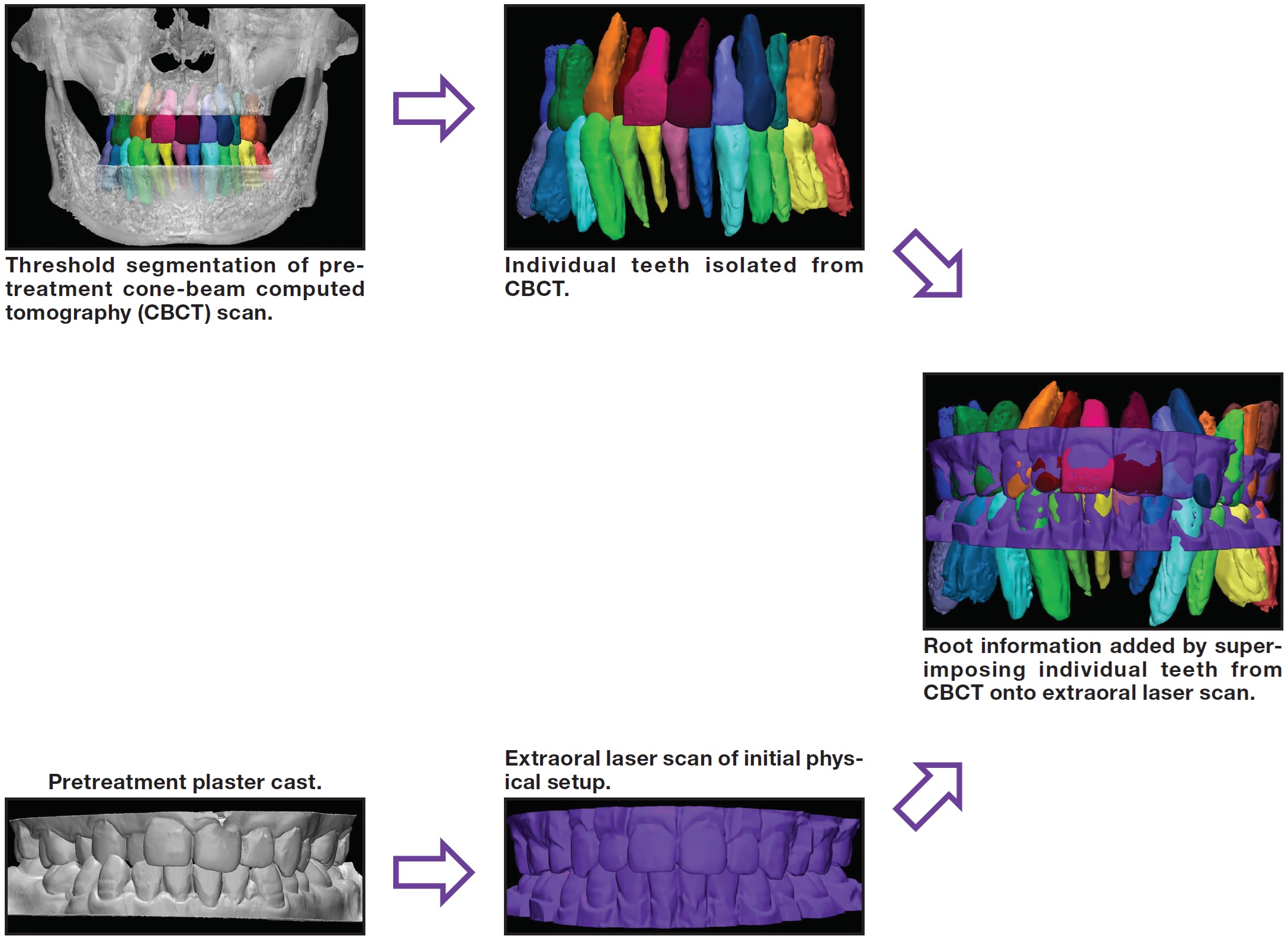
Fig. 2 Superimposition process used to generate root positions for initial virtual setup.
A crude superimposition was performed by selecting and superimposing three points that were in roughly the same anatomical positions on the CBCT and laser-scanned crowns, thus bringing the virtual models relatively close to the desired relationship.
Fine, global registration was performed with an iterative closest-point algorithm that used 100% of the points making up the 3D models. Since each CBCT and laser-scanned crown is built from more than 5,000 points, this algorithm yields the minimum displacement between points. Color-displacement maps were created to quantitatively confirm the accuracy of the superimposition by measuring the displacement between the closest points of the CBCT and laser-scanned crowns. The superimposition was considered accurate when the points making up the crowns had an average distance error of less than .1mm.19,20
Adding the roots to the initial setup allowed a more thorough evaluation of the alignment of the crowns, as well as the angulation and inclination of the teeth. Although the initial cast setup was considered satisfactory to the authors, the addition of the roots clearly revealed that the lower left canine had excessive distal crown tip, the lower left second premolar and central incisor had excessive mesial crown tip, and the upper left second premolar had excessive lingual crown torque (Fig. 3).
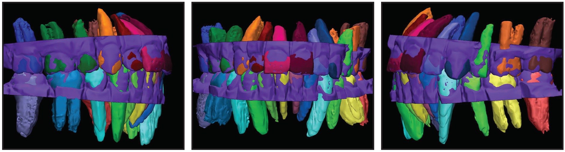
Fig. 3 Errors in angulation of lower left canine, lower left second premolar, and lower left central incisor and in inclination of upper left second premolar detected when dental roots were added to initial setup.
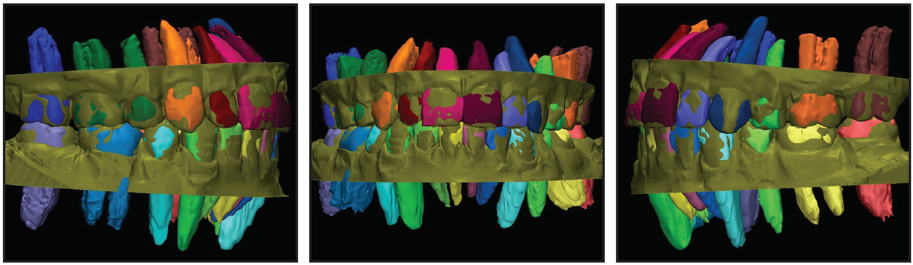
After appropriate alterations to the physical setup were made, a new extraoral scan and crown superimposition were performed to create a final setup (Fig. 4), which was later used for the fabrication of customized orthodontic appliances.
Discussion
The ABO deducts points from submitted cases if adjacent dental roots are not parallel with or in contact with each other, indicating that proper root positions are a priority of orthodontic treatment. The method described here adds roots from a CBCT scan by superimposing the crowns of individual teeth onto a digital scan of an ideal crown setup. CBCT has been found to display dentofacial structures in a 1:1 ratio - precise enough that any distortions are clinically insignificant.9,22
Even if the final setup is ultimately dictated by the crown positions, this procedure will help identify errors in crown angulation and inclination that might have been missed during initial physical inspection. As our case demonstrates, the ability to visualize the roots allows the clinician to improve the ideal 3D setup. Of course, the orthodontist may decide to leave the roots uncorrected in certain patients to accommodate crown positions, especially in cases involving root dilacerations or abnormal crown shapes.
Although our demonstration involved an extraoral laser scan of a physical setup, we believe the procedure will work even better on virtual setups because the evaluation, modification, and confirmation of root position can be accomplished instantaneously, without the need for additional extraoral scans. One disadvantage is that a substantial amount of time and effort is required for the threshold segmentation of each tooth from the complex craniofacial bony structures and for the superimposition of individual crowns. Further advances in imaging technology and processing software may make this process much faster and easier to perform.
FOOTNOTES
- *Registered trademark of Align Technology, Inc., Santa Clara, CA; www.aligntech.com.
- **Trademark of 3M Unitek, Monrovia, CA; www.3Munitek.com.
- ***Ormco Corporation, Orange, CA; www.ormco.com.
- †Sirona Dental Systems, Inc., Long Island City, NY; www.sirona.com.
- ‡Registered trademark of Materialise, Leuven, Belgium; www.materialise.com.
- ††MotionView Software, LLC, Hixson, TN; motionview3d.com.
REFERENCES
- 1. Dewel, B.F.: Clinical observations on the axial inclination of teeth, Am. J. Orthod. 35:98-115, 1949.
- 2. Carlsson, R. and Ronnerman, A.: Crown-root angles of upper central incisors, Am. J. Orthod. 64:147-154, 1973.
- 3. Bryant, R.M.; Sadowsky, P.L.; and Hazelrig, J.B.: Variability in three morphologic features of the permanent maxillary central incisor, Am. J. Orthod. 86:25-32, 1984.
- 4. Germane, N.; Bentley, B.E.; and Isaacson, R.J.: Three biologic variables modifying faciolingual tooth angulation by straight-wire appliances, Am. J. Orthod. 96:312-319, 1989.
- 5. Mayoral, G.: Treatment results with light wires studied by panoramic radiography, Am. J. Orthod. 81:489-497, 1982.
- 6. Rothe, L.E.; Bollen, A.M.; Little, R.M.; Herring, S.W.; Chaison, J.B.; Chen, C.S.; and Hollender, L.G.: Trabecular and cortical bone as risk factors for orthodontic relapse, Am. J. Orthod. 130:476-484, 2006.
- 7. Guo, H.; Zhou, J.; Bai, Y.; and Li, S.: A three-dimensional setup model with dental roots, J. Clin. Orthod. 45:209-216, 2011.
- 8. Keim, R.G.; Gottlieb, E.L.; Nelson, A.H.; and Vogels, D.S.: 2008 JCO Study of Orthodontic Diagnosis and Treatment Procedures, Part 1: Results and trends, J. Clin. Orthod. 42:625-640, 2008.
- 9. Lagravère, M.O.; Carey, J.; Toogood, R.W.; and Major, P.W.: Three-dimensional accuracy of measurements made with software on cone-beam computed tomography images, Am. J. Orthod. 134:112-116, 2008.
- 10. Mckee, I.W.; Glover, K.E.; Williamson, P.C.; Lam, E.W.; Heo, G.; and Major, P.W.: The effect of vertical and horizontal head positioning in panoramic radiography on mesiodistal tooth angulations, Angle Orthod. 71:442-451, 2001.
- 11. Garcia-Figueroa, M.A.; Raboud, D.W.; Lam, E.W.; Heo, G.; and Major, P.W.: Effect of buccolingual root angulation on the mesiodistal angulation shown on panoramic radiographs, Am. J. Orthod. 134:93-99, 2008.
- 12. Owens, A.M. and Johal, A.: Near-end of treatment panoramic radiograph in the assessment of mesiodistal root angulation, Angle Orthod. 78:475-481, 2008.
- 13. Tong, H.; Enciso, R.; Van Elslande, D.; Major, P.W.; and Sameshima, G.T.: A new method to measure mesiodistal angulation and faciolingual inclination of each whole tooth with volumetric cone-beam computed tomography images, Am. J. Orthod. 142:133-143, 2012.
- 14. Tong, H.; Kwon, D.; Shi, J.; Sakai, N.; Enciso, R.; and Sameshima, G.T.: Mesiodistal angulation and faciolingual inclination of each whole tooth in 3-dimensional space in patients with near-normal occlusion, Am. J. Orthod. 141:604-617, 2012.
- 15. Grauer, D.; Wiechmann, D.; Heymann, G.C.; and Swift, E.J.: Computer-aided design/computer-aided manufacturing technology in customized orthodontic appliances, J. Esthet. Restor. Dent. 24:3-9, 2012.
- 16. Wiechmann, D.; Rummel, V.; Thalheim, A.; Simon, J.; and Wiechmann, L.: Customized brackets and archwires for lingual orthodontic treatment, Am. J. Orthod. 124:593-599, 2003.
- 17. Gracco, A. and Tracey, S.: The Insignia system of customized orthodontics, J. Clin. Orthod. 45:442-451, 2011.
- 18. Sachdeva, R.C.: SureSmile technology in a patient-centered orthodontic practice, J. Clin. Orthod. 35:245-253, 2001.
- 19. Lee, R.J.; Pham, J.; Choy, M.; Weissheimer, A.; Dougherty, H.L. Jr.; Sameshima, G.T.; and Tong, H.: Monitoring of typodont root movement via crown superimposition of single cone-beam computed tomography and consecutive intraoral scans, Am. J. Orthod. 145:399-409, 2014.
- 20. Lee, R.J.; Weissheimer, A.; Pham, J.; Go, L.; de Menezes, L.; Redmond, W.R.; Loos, J.F.; Sameshima, G.T.; and Tong, H.: Three-dimensional monitoring of root movement during orthodontic treatment, Am. J. Orthod. 147:132-142, 2015.
- 21. National Electrical Manufacturers Association: DICOM digital imaging and communications in medicine, 2011, medical. nema.org/Dicom/2011/11_01pu.pdf, accessed Aug. 24, 2015.
- 22. Lascala, C.A.; Panella, J.; and Marques, M.M.: Analysis of the accuracy of linear measurements obtained by cone beam computed tomography (CBCT-NewTom), Dentomaxillofac. Radiol. 33:291-294, 2004.
-
 MR. LEE
 -
 DR. PHAM
 -
 DR. WEISSHEIMER
 -
 DR. TONG
Mr. Lee is a student, School of Dentistry, University of California, Los Angeles. Dr. Pham is a biomedical and computer engineer and in the private practice of orthodontics in Huntington Beach, CA. Dr. Weissheimer is a Professor, Department of Orthodontics, Pontifical Catholic University of Rio Grande do Sul, Porto Alegre, Rio Grande do Sul, Brazil. Dr. Tong is a Clinical Assistant Professor, Advanced Orthodontic Program, Herman Ostrow School of Dentistry, University of Southern California, 925 W. 34th St., Los Angeles, CA 90089; e-mail: drhstong@gmail.com.