Uses of the Vertical Slot in Orthodontic Brackets
Many orthodontists have discovered the utility of a simple, vertically positioned square hole in an orthodontic bracket. The vertical slot, or V-slot, permits the simple addition of a variety of useful auxiliaries and biomechanical adjuncts (Fig. 1). As Gianelly once said in a personal communication, "I don't understand why you wouldn't want a vertical slot in your bracket, whatever bracket you choose; it's free."
Unfortunately, little has been published specifically on the use of V-slots, other than in the Begg system1 and Gianelly's Bidimensional technique.2 Although some clinicians might assume that the addition of a V-slot would raise the profile of the orthodontic bracket, thus increasing patient discomfort, recent design improvements have resulted in a lower profile in both standard and self-ligating brackets.3,4 This article describes various applications of the V-slot in an edgewise bracket system.
Similar articles from the archive:
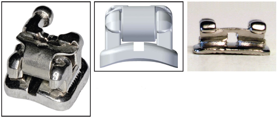
Fig. 1 Brackets with vertical slot (V-slot) permit insertion of various auxiliaries (images courtesy of American Orthodontics*).
Uprighting Springs
Uprighting springs are typically used with V-slot single brackets or Begg brackets to upright the roots of tipped teeth. In the edgewise technique, these springs provide a reversible and versatile method of controlling anchorage by increasing resistance to sliding.5 The crown of the tooth is tipped until the opposite internal angles of the bracket slot contact the archwire, creating a binding effect (Fig. 2).
Uprighting springs are a less costly and invasive alternative to temporary anchorage devices or site-specific surgical procedures such as corticotomy or microperforation of the cortical bone.
Gianelly's Bidimensional protocol is especially suited to Class II extraction cases, in which lower posterior teeth need to be protracted into the extraction spaces.6 The protraction is accomplished with nickel titanium closed-coil springs while the position of the anterior teeth is maintained, thus actually losing or "burning" posterior anchorage (Fig. 3).
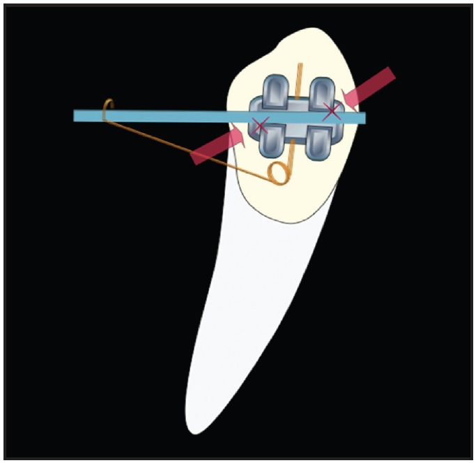
Fig. 2 Uprighting spring used to control anchorage in edgewise technique.
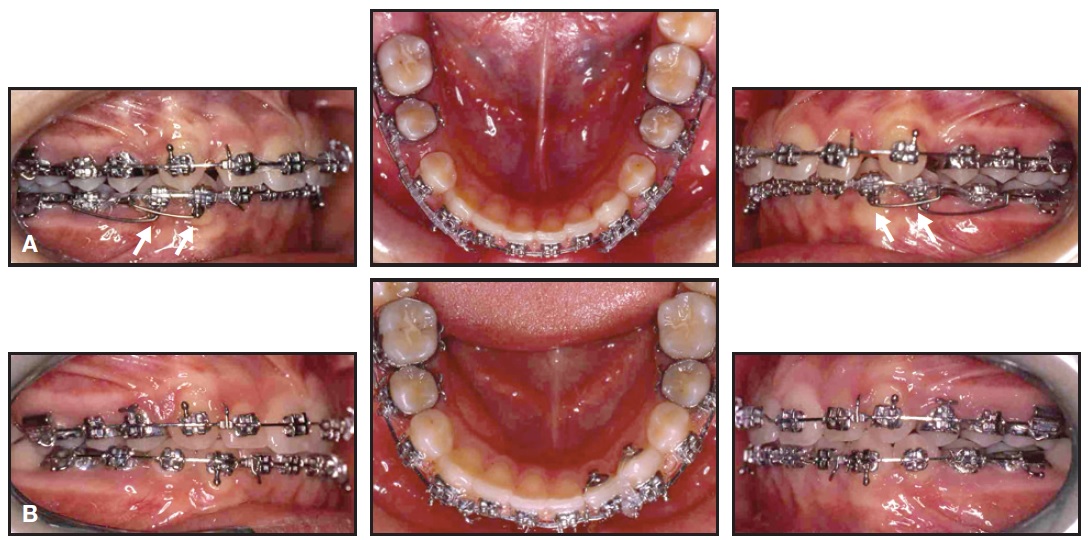
Fig. 3 12-year-old female patient with Class II, division 1 malocclusion. A. Symmetrical mandibular molar protraction with uprighting springs. B. After four months of treatment.
An .018" x .022" highly tempered stainless steel archwire is placed with 10-15º of lingual root torque (for an .018" prescription) in the anterior segment. The uprighting springs are inserted into the canine V-slots and oriented to produce a mesial component of force while Class I intra-arch sliding mechanics are employed. The same procedure can be used to enhance anterior anchorage during molar protraction for asymmetrical space closure.7
Uprighting springs can also be employed to counteract the mesial mandibular forces and undesirable labial tipping of lower anterior teeth produced by Class II elastics or appliances such as the Herbst** or Forsus***. In the Bidimensional technique, the detrimental aspects of Class II elastics are countered with an .018" x .022" archwire with 10-15º of lingual crown torque, a reverse curve of Spee, and 10º of molar "toe-in", combined with uprighting springs inserted into the premolar V-slots and oriented to create distal moments (Fig. 4).

Fig. 4 A. 11-year-old male patient with Class II, division 1 malocclusion. B. Uprighting springs used to counteract mesial force on mandibular dentition and unintended labial tipping of lower anterior teeth from Class II elastics. C. After eight months of treatment.
Interarch elastics and uprighting springs can be a useful combination in a case with a midline discrepancy of 2mm or less. After minor interproximal reduction is performed in the anterior segments of the maxillary and mandibular arches, four uprighting springs are inserted, usually on the canines (Fig. 5).
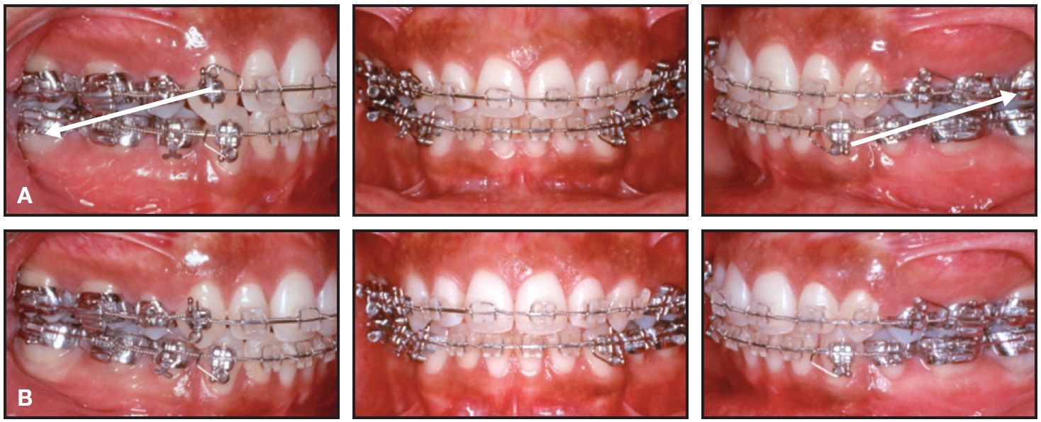
Fig. 5 14-year-old male patient treated with four premolar extractions. Toward end of treatment, maxillary midline was deviated slightly left and mandibular midline slightly right. A. After minor interproximal reduction of both anterior segments, uprighting springs oriented to produce distal moments on upper right and lower left canines and mesial moments on lower right canine and upper left first premolar (upper left canine had esthetic bracket without V-slot); Class II elastics worn on right side and Class III elastics on left. B. After one month of treatment (case treated by Dr. Anthony A. Gianelly and published with permission).
Class II elastics are worn on one side and Class III elastics on the opposite side of the arch, with tooth movement expedited by the uprighting springs.
Rotating Springs
Rotating springs made of round wire can also be used with V-slots to correct individual dental rotations1 (Fig. 6). This not only avoids the limitations of passive self-ligating brackets, but precludes the need for counter-rotational Lewis wings on narrow brackets. Since superelastic wire materials have diminished the interbracket-distance advantage of single brackets, small twin brackets with V-slots appear to provide more versatility and control.
The Compliance+ spring* was designed for two different applications. Its force is derived from a combination with intermaxillary Class II, Class III, or delta (triangular) elastics. If the elastic hook of the Compliance+ spring is adjusted to protrude slightly into the buccal tissue, it will cause minor soft-tissue irritation that can be alleviated simply by wearing the elastics (Fig. 7). The spring auxiliary slides onto the main archwire before the leg of the spring is inserted into the V-slot. The archwire must then be tied into the bracket with a stainless steel ligature to prevent it from becoming dislodged by the spring. When the Compliance+ spring is placed over a round base archwire, it produces single-tooth labial root torque. This is often useful after a palatally impacted canine has been moved into the arch, though the root will still require labial movement. The Compliance+ spring can also provide labial root torque for lingually positioned upper or lower lateral incisor roots. To avoid generating unwanted labial torque, the spring must be used with a rectangular base archwire.
Power Arms, T-Pins, and Elastic Hooks
Orthodontic patients frequently complain about protruding ball hooks, which can be annoying in terms of appearance, comfort, and oral hygiene. V-slots permit the addition of power arms, T-pins, or elastic hooks on any individual teeth (Fig. 8).
The patient is less likely to wear elastics in the wrong configuration (such as Class II instead of Class III) when these hooks are added only where forces are required, and they can easily be removed after use. The clinician is able to prescribe intermaxillary elastics to be worn from the maxillary lateral incisors instead of the canines ("long Class II"), from the lower second premolars ("short Class II"), or even in zig-zag or "spaghetti" configurations on nearly every tooth to improve final intercuspation. Individual hooks eliminate the inconvenience of fumbling with soldered or crimpable hooks.
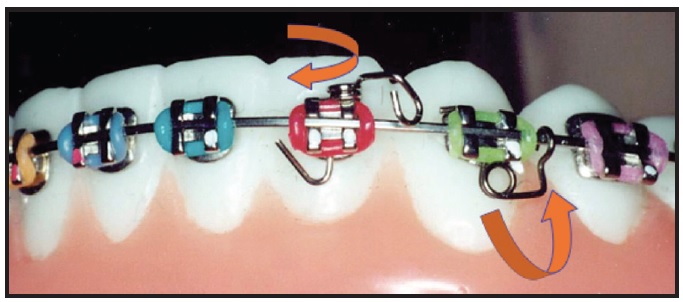
Fig. 6 Rotating springs used to facilitate correction of severe rotations, improve root parallelism, and enhance anchorage.
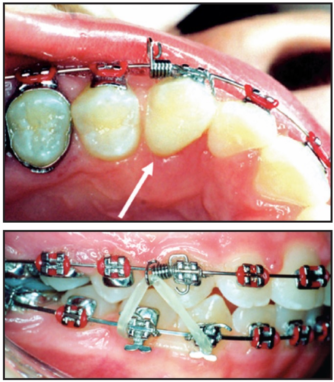
Fig. 7 Compliance+ spring* promotes patient compliance by causing minor soft-tissue irritation when elastics are not worn.
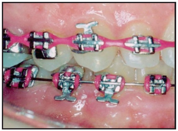
Fig. 8 Addition of individual hooks and pins to V-slots helps keep patient from orienting elastics in wrong configuration.
Longer power arms can be inserted into V-slots to allow the application of orthodontic forces closer to the center of resistance of the tooth for more efficient movement. The power arms will also lie closer to the facial surface of the tooth than a ball hook would be, thus reducing the rotational potential of retraction forces. For instance, in an extraction case, maximum anchorage for canine or en masse anterior retraction may be derived from a miniscrew inserted mesial to the first molars. If forces were applied from the miniscrew directly to the canine bracket, the consequent rotational moment might cause more crown tipping (Fig. 9A). If the force is instead applied to a power arm inserted in the V-slot of the canine bracket, a more translatory movement is produced (Fig. 9B).
Power pins, T-pins, and elastic hooks can also act as substitutes for labor-intensive soldered or crimpable hooks in patients undergoing orthognathic surgery (Fig. 10). Power pins are easily inserted for temporary ligation of a splint during surgery, or for elastic wear after surgery, and can be removed when no longer needed.
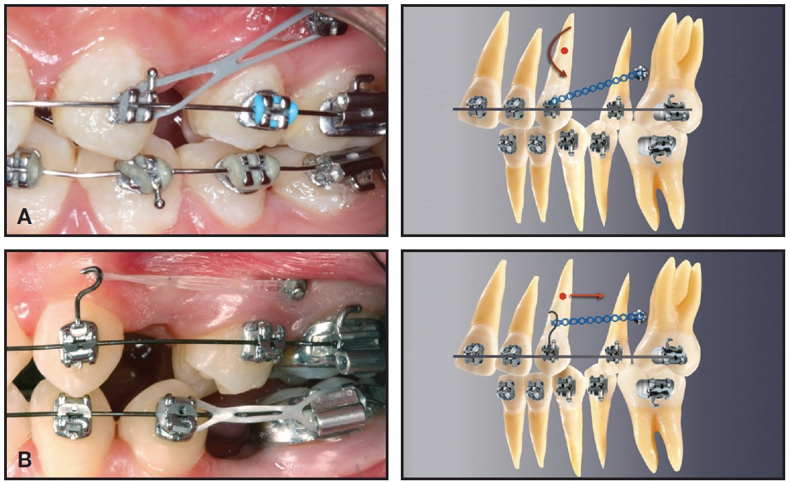
Fig. 9 Compared to conventional ball hook (A), application of force to power arm inserted in V-slot of canine bracket (B) allows more translatory and efficient movement (cases treated by Dr. Mattia Fontana and published with permission).

Fig. 10 Power pins and Kobayashi ligatures inserted in V-slots substitute for soldered or crimpable hooks in surgical-orthodontic patient.
V-Tie Ligation
V-slots seem indispensable if for no other purpose than to allow insertion of ligature wires or elastic threads for correction of severely rotated or displaced teeth (Fig. 11). If the popular low-friction mechanics are desired, the least friction and widest interbracket distance for initial alignment would be obtained from a loosely tied stainless steel ligature, especially if it is inserted through a V-slot and simply looped around the archwire ("sling tie" or "V-tie").
The V-slot is particularly useful when an ectopic or blocked-out tooth cannot be tied in conventionally, or when a tooth is significantly misaligned after a bracket has been lost between appointments. Instead of applying excessive force to fully engage the archwire into the bracket, the clinician can pass a stainless steel ligature wire or elastic thread through the V-slot and around the archwire. As the ligature wire is reactivated or the thread is replaced at each appointment, the tooth will gradually be drawn back into the arch (Fig. 12). The V-tie may thus avoid the need to step back in archwire dimension, potentially reducing treatment time and expense.
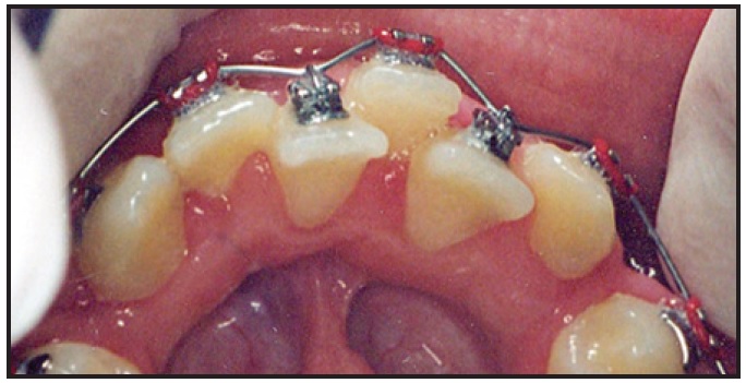
Fig. 11 Stainless steel ligature inserted through V-slot and looped around archwire (“V-tie”) to direct positioning of severely displaced teeth.
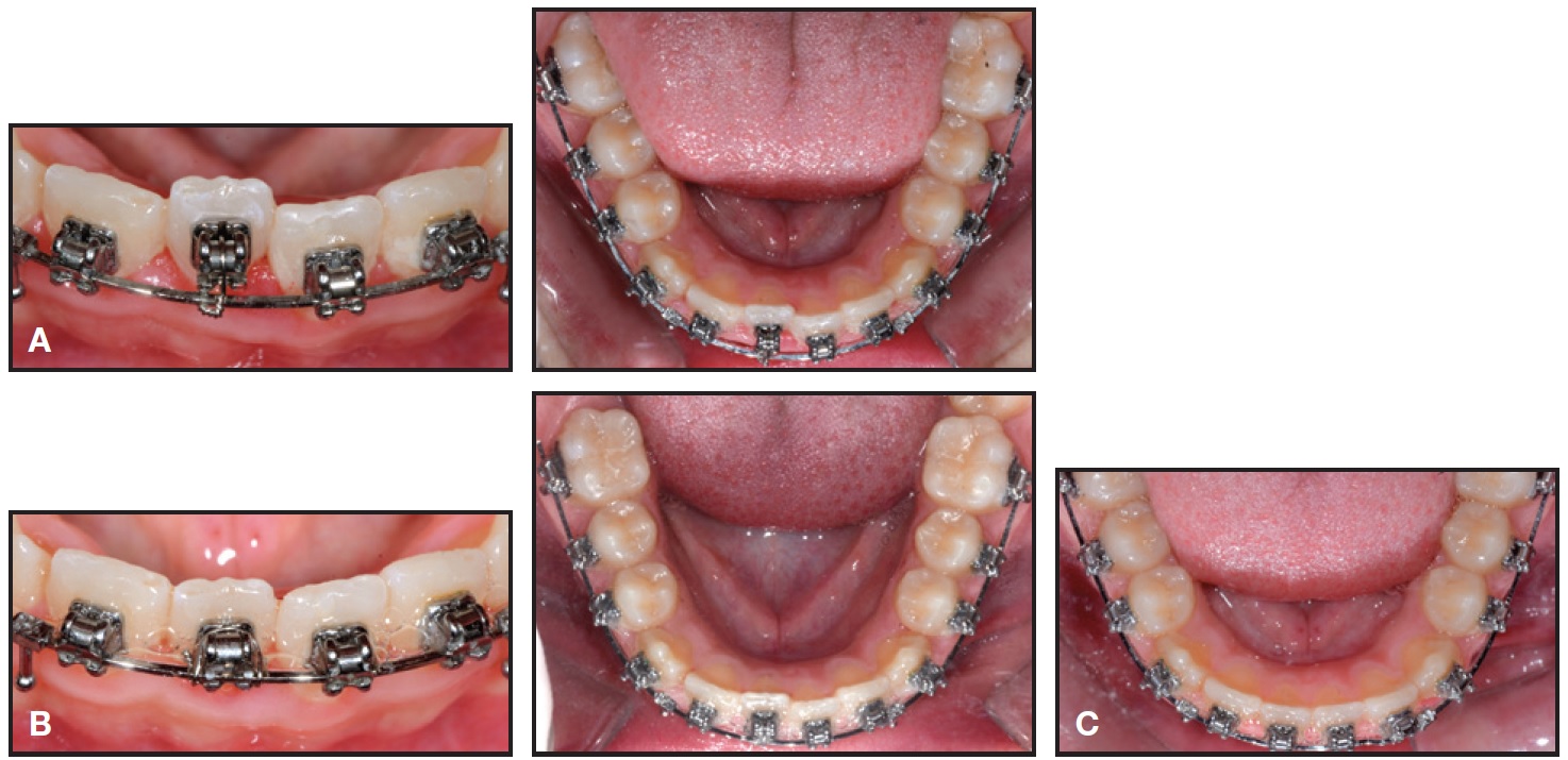
Fig. 12 12-year-old male patient with Class II, division 1 malocclusion. A. V-tie used on displaced lower right central incisor. B. After one month of treatment. C. Incisor drawn back into arch after two months of treatment.
Overlay Wires
It is not always possible to bracket second molars early, since they may not erupt until later in treatment when orthodontic mechanics have progressed to large dimension rectangular wires. Buccally erupting second molars are especially challenging if the first-molar brackets are not convertible or self-ligating. In that situation, the clinician is often required to return to undersize or more elastic wires to "gather up" the displaced second molars, with a consequent loss of three-dimensional control throughout the dental arch. A possible solution is to keep the larger rectangular wire from first molar to first molar and add an overlay wire such as .014" superelastic nickel titanium from the second molars, ligated with stainless steel ligatures through the V-slots of the premolars and canines8 (Fig. 13). Similarly, a V-tied overlay wire can also be added to the base archwire to facilitate the addition of a second expanded or reverse-curve wire for leveling during alignment with a small-diameter base wire.
Alternative Methods
As an alternative to V-slots, Binder developed uprighting and rotating springs for use with standard and preadjusted edgewise brackets.9 A different method proposed by Jain involved a modification of Begg uprighting springs for preadjusted edgewise brackets.10 Although the mechanical principles are similar to those described here, these systems require greater manual skills and can be utilized only with uprighting and rotating springs.
Conclusion
The use of V-slots makes any edgewise technique more efficient and versatile, while making the appliance more comfortable for the patient.
FOOTNOTES
- *American Orthodontics, Sheboygan, WI; www.americanortho.com.
- **Dentaurum Inc., Newtown, PA; www.Dentaurum.com.
- ***3M Unitek, Monrovia, CA; www.3Munitek.com.
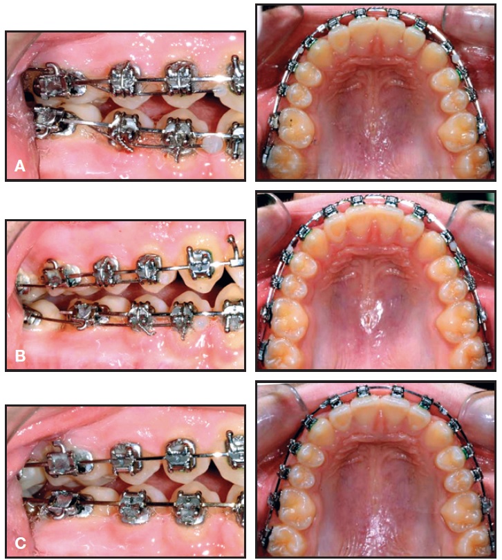
Fig. 13 12-year-old male patient with Class II, division 1 malocclusion. A. Base .018" × .022" stainless steel archwires combined with .014" superelastic wires, overlaid from second molars to second premolars and ligated to V-slots of first and second premolars, for extrusion and transverse control. B. New .018" × .022" archwires incorporating second molars after two months of treatment. C. After four months of treatment.
REFERENCES
- 1. Kesling, P.C.: Begg theory and technique: Past, present, and future, in New Vistas in Orthodontics, ed. L.E. Johnston Jr., Lea and Febiger, Philadelphia, 1985.
- 2. Gianelly, A.: Bidimensional Technique: Theory and Practice, GAC International, Islandia, NY, 2000.
- 3. Bowman, S.J. and Carano, A.: Addressing concerns with finished cases: The development of the butterfly bracket system. Part II, J. Ind. Orthod. Soc. 36:135-139, 2003.
- 4. Bowman, S.J. and Carano, A.: The butterfly bracket system, J. Clin. Orthod. 38:274-287, 2004.
- 5. Cozzani, M. and Mazzotta, L.: Bidi-self: La tecnica bidimensional con brackets de autoligado, Rev. Esp. Ortod. 42:240-246, 2012.
- 6. Gianelly, A.A.; Smith, J.B.; Bednar, J.R.; and Dietz, V.S.: Asymmetric space closure, Am. J. Orthod. 90:335-341,1986.
- 7. Cozzani, M.; Rinchuse, D.J.; Mazzotta, L.; and Cozzani, P.: Asymmetric mandibular molar protraction with conventional mechanics, J. Clin. Orthod. 49:304-311, 2015.
- 8. Menini, A.; Cozzani, P.; and Cozzani, M.: Eruption control of maxillary second molars with a segmental overlay wire, J. Clin. Orthod. 46:45-47, 2012.
- 9. Binder, R.E.: Addition of uprighting and rotating springs to standard edgewise or preadjusted brackets, J. Clin. Orthod. 36:279-280, 2002.
- 10. Jain, S.: A modified Begg uprighting spring for preadjusted edgewise brackets, J. Clin. Orthod. 42:652, 2008.


