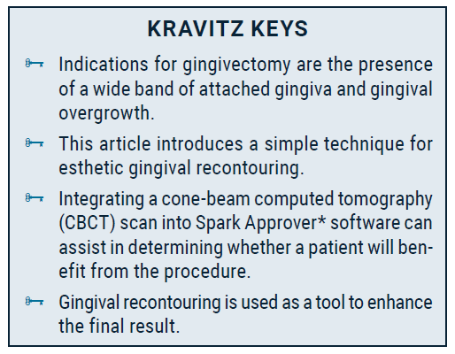
Digital Planning for Gingival Recontouring after Clear Aligner Treatment
Modern esthetic dentistry is rooted in Lombardi’s 1973 article applying the principles of visual perception to the design of appealing dentures.1 Twenty-five years later, Zachrisson revisited these concepts,2 outlining the following elements of smile esthetics:
- Crown lengths of maxillary and mandibular
incisors - Incisal-edge contours
- Axial inclinations of all maxillary and mandibular
incisors - Midlines (upper, lower, labial, and facial)
- Crown torque (canines, premolars, and molars
on both sides) - Smile line (rest position and full smile)
- Right-left symmetry of crown shapes and sizes
and gingival margin levels
While most of these factors can be addressed with orthodontic treatment—whether with fixed appliances, as Zachrisson proposed, or with clear aligners, as demonstrated in this article—gingival recontouring is often required to achieve ideal crown lengths and right-left symmetry of crown shapes.3,4
Relatively few orthodontists are currently harnessing the benefits of gingivectomy, primarily due to the challenges involved in integrating it safely and effectively into their practices. This article presents a streamlined approach to determining whether gingivectomy is indicated, as well as a straightforward procedure for performing it in the office, using digital technology to achieve predictable outcomes without the need for surgical templates.
Similar articles from the archive:
- THE READERS' CORNER Cosmetic Finishing February 2022
- Clinical Uses of Diode Lasers in Orthodontics May 2004
Case Report
A 21-year-old female presented for orthodontic treatment due to the perceived juvenile appearance of her dentition. Clinical examination found a symmetrical face and straight profile, with flared upper and lower incisors in smiling (Fig. 1).

Fig. 1 21-year-old female patient with anterior spacing in both arches, flared upper and lower incisors in smiling, proclined lower incisors, and gingival overgrowth before treatment.
The patient exhibited bilateral Class I molar and canine relationships. Anterior spaces were present in both arches, and excessive gingival tissue was noted, along with short clinical crowns and right-left asymmetry of the upper central and lateral incisors. A panoramic radiograph showed predominantly healthy teeth, with a previous root canal on the upper left first molar. Cephalometric analysis indicated a skeletal Class I relationship, proclined lower incisors (IMPA = 109°), and normally inclined upper incisors (Table 1).

The proposed treatment plan consisted of two parts: first, Spark* clear aligners would be used to close the spaces and establish proper axial inclination of the maxillary incisors, while preserving the smile arc5; subsequently, gingival recontouring would be performed to improve the height-width ratio and symmetry of the upper incisors.
A digital setup was performed using Spark Approver software (Fig. 2). The anterior spaces would be closed through translatory retraction of the upper incisors and retroclination of the lower incisors, which would also improve the interincisal angle. The digital plan included intrusion of the lower incisors to counteract the relative extrusion and increased overbite that could result from the change in torque; intrusion of the upper incisors was ruled out, however, because it can flatten the smile arc, potentially worsening smile esthetics.6 Horizontal rectangular attachments were added on the lower molars and premolars to counteract any resistance to intrusion from the lower incisors, and bite ramps were planned for the upper canines to support lower-incisor intrusion and allow for lower-posterior eruption. To avoid anterior premature contacts and ensure predictable and permanent space closure, an overjet of 2mm and an overbite of no more than 1mm were incorporated into the plan.
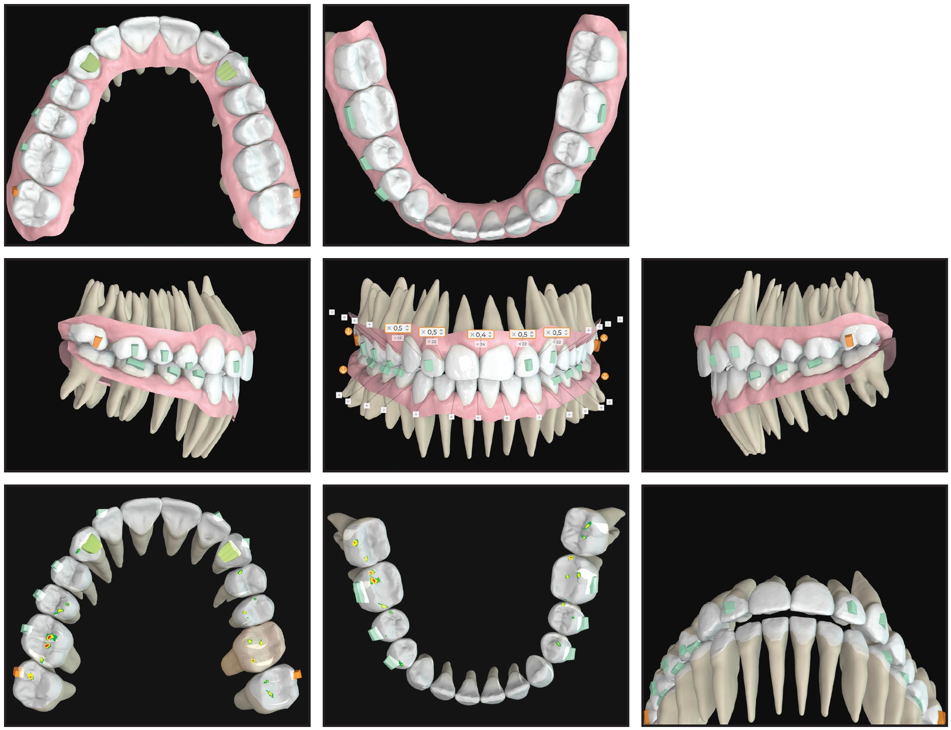
Fig. 2 Digital planning of tooth movements, interproximal reduction, and aligner attachments using Spark Approver* software; occlusal contacts planned to prevent anterior interferences.
Interproximal reduction was performed on the upper central and lateral incisors to narrow the incisal embrasures. Twenty-nine sets of aligners were delivered, to be changed every seven days, and passive aligners were worn for another 10 weeks for stabilization. After 39 weeks of treatment, the anterior spaces were closed, a proper occlusion was preserved, and normal overjet and overbite were achieved. Facial esthetics were also improved by the parallel torque of the canines and premolars.
Even after orthodontic treatment, however, the length-to-width ratio of the central incisors and the asymmetrical gingival contours of the anterior teeth negatively affected the patient’s smile esthetics. Therefore, we proceeded with the planned gingival recontouring.
Gingival Recontouring Procedure
Indications for a gingivectomy include a wide band of attached gingiva and gingival overgrowth (Fig. 3). The keratinized or attached gingiva is the part of the gum tightly bound to the underlying bone and teeth, forming a collar-like band around the teeth. In contrast, the movable mucosa is flexible enough to allow movement of the lips and cheeks. The gingival contours must remain within the attached gingiva, which anchors the mucosa against the forces exerted by the lips and cheeks; if this protective collar is removed, gingival recession can occur.
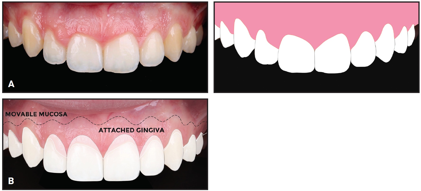
Fig. 3 A. Outline of incisal edges and gingival contours, showing short crown lengths and right-left asymmetry of upper incisors due to gingival overgrowth. B. New gingival margins drawn within boundaries of attached gingiva.
Traditional methods for evaluating gingival overgrowth include bone sounding and comparison of clinically observed crown lengths with those depicted in two-dimensional radiographs. CBCT now offers increased precision and improved visualization of bony anatomy and tooth morphology. The integration of CBCT with Spark Approver software facilitates a comparison of anatomical and clinical crowns, providing a straightforward method of assessing potential gingival overgrowth (Fig. 4). In our case, digital analysis revealed an ideal length-to-width ratio of the upper central incisors, which were partially concealed beneath the excessive gingival tissue. Because of the gingival overgrowth and the wide band of attached gingiva, gingivectomy was deemed appropriate.
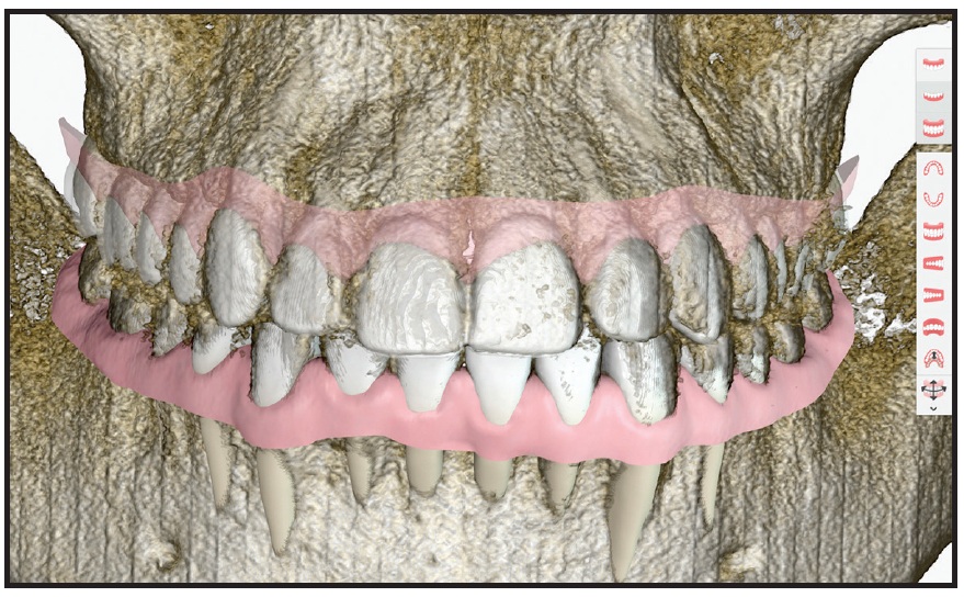
Fig. 4 Integration of cone-beam computed tomography scan into Spark Approver software.
To simplify the procedure and avoid the need for a cutting template, we use the gingival zenith as a guideline for recontouring (Fig. 5). This technique enables the orthodontist to perform the procedure as soon as it is indicated, with predictable results. The zenith is the highest point of the gingival contour; on a central incisor, it is slightly distal to the long axis of the tooth. Once the gingival zenith is located, it can be marked by punching the gum tissue with the tip of an electrotome.
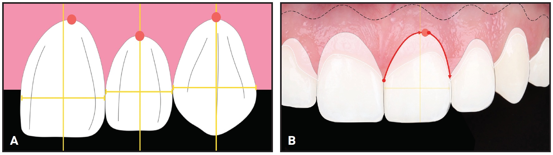
Fig. 5 A. Location of gingival zenith (yellow vertical line = long axis of tooth, red dot = gingival zenith). B. Technique for determining new gingival contours: after gingival zenith is marked (red dot), curved line is drawn from mesial tip of papilla through zenith to distal tip of papilla (red arrows).
An electrotome (Fig. 6) or laser is recommended for the gingival recontouring. Because both instruments cut tissue by transforming electrical energy into heat, they cauterize as they cut, thus reducing the risk of bleeding and facilitating quicker healing. Immediate wound sealing also keeps the operating field dry, enhancing visibility and precision.
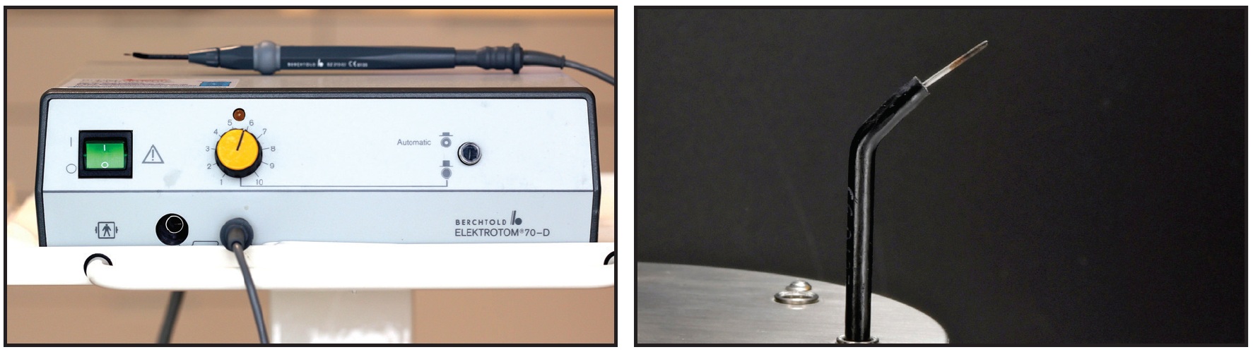
Fig. 6 Bühler Instruments Electrotome 70-D** used for gingival recontouring.
The procedure is performed under local anesthesia. Holding the electrotome at a 90° angle, the new gingival margin is cut, tracing a curve that extends from the mesial tip of the papilla to the marked zenith and then to the distal tip of the papilla (Fig. 7). Since some regrowth is expected, the tissue can be removed generously as long as the new margin stays within the attached gingiva. Next, the new gingival contours are beveled at a 45° angle to the tooth surface, and the tissue is debulked to create a more natural appearance and minimize regrowth.
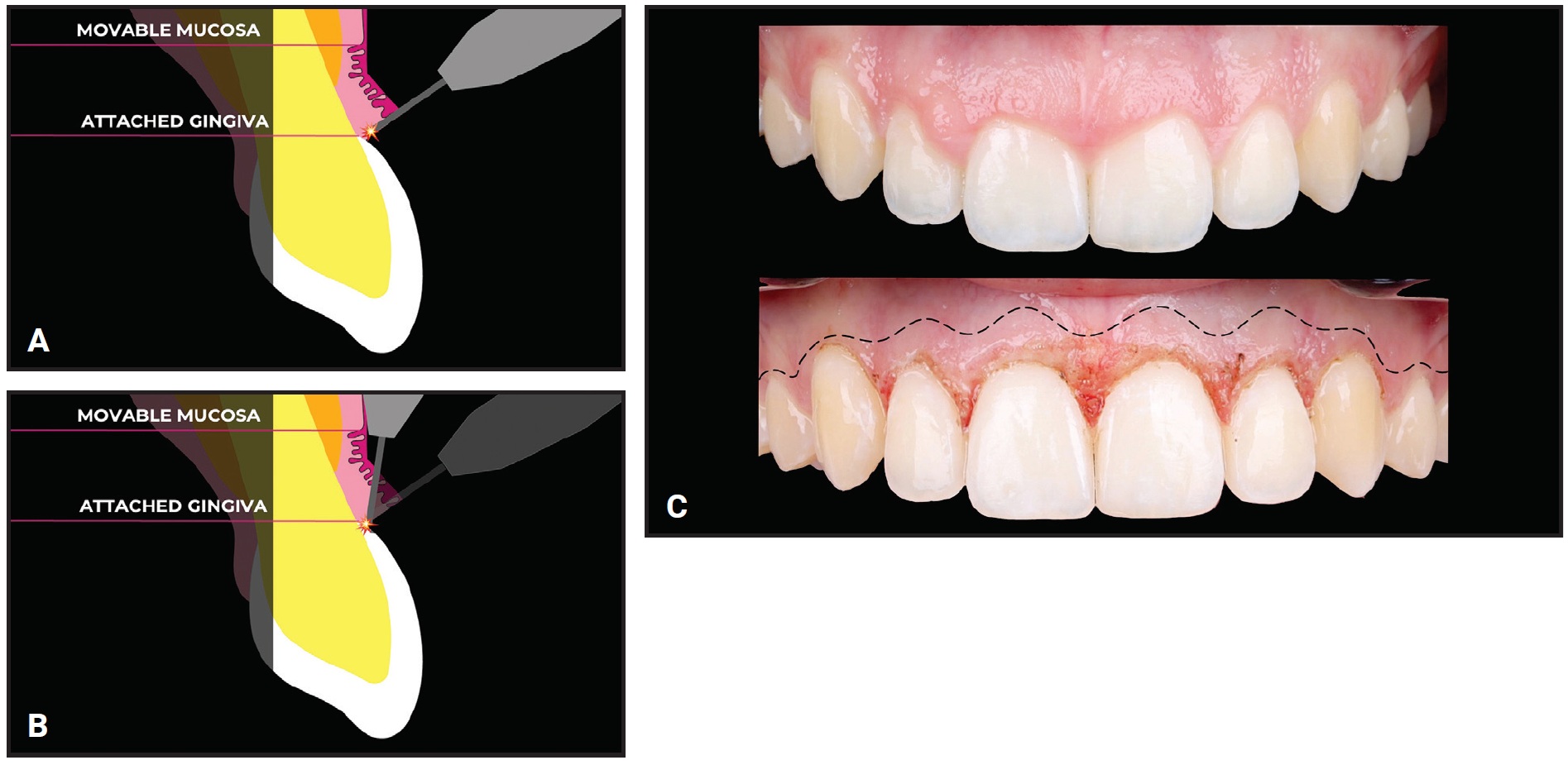
Fig. 7 Gingival recontouring procedure. A. New margins drawn with instrument held at 90° angle. B. Bevel made at 45° angle to tooth surface. C. Comparison of pretreatment (above) and post-treatment (below) gingival margins (dotted line = mucogingival junction separating movable mucosa from attached gingiva).
In our case, the gums had healed completely by one week after the procedure, and gingival regrowth stayed within the expected range of .5-1mm. After the combination of orthodontic treatment and gingival recontouring, the smile met all the esthetic criteria listed by Zachrisson, and the patient reported improved satisfaction with her appearance (Fig. 8A and 8B).
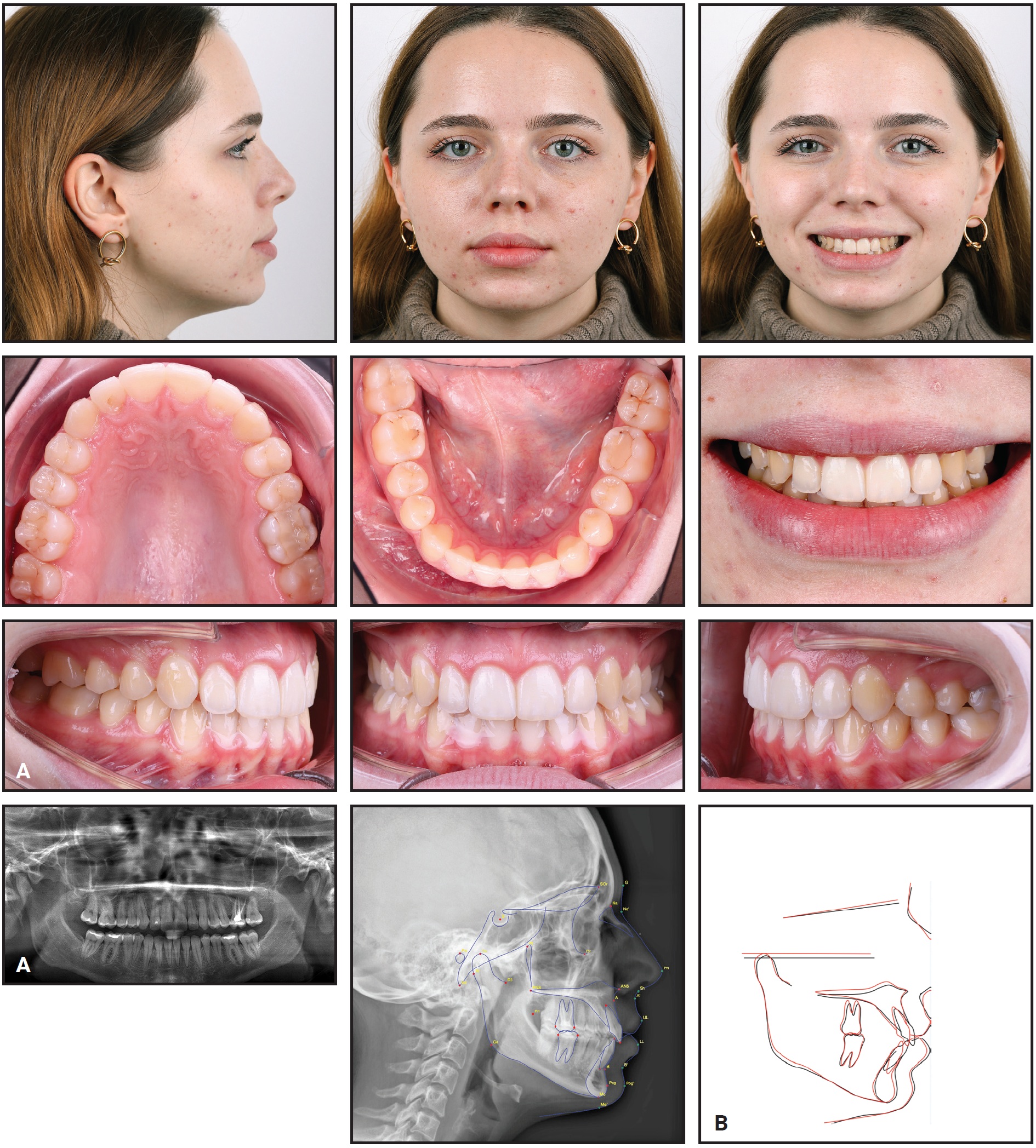
Fig. 8 A. Patient after 39 weeks of clear aligner treatment, showing closed anterior spaces, sufficient lower-incisor intrusion, proper posterior occlusion, and adequate overjet and overbite. B. Superimposition of pretreatment (black) and post-treatment (red) cephalometric tracings, showing ideal upper-incisor inclination, reduced lower-incisor inclination, and improved interincisal angle (continued in next image).
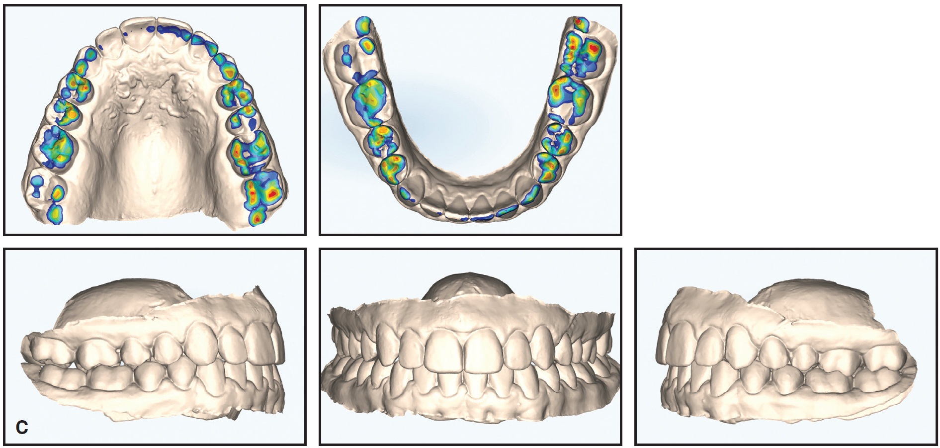
Fig. 8 (cont.) C. Post-treatment digital models, showing preserved Class I occlusion, centered midlines, occlusal contacts well distributed across posterior teeth, and adequate interincisal clearance.
Conclusion
Once the teeth have been well aligned and an acceptable occlusion has been achieved, finishing touches to the gingiva can further improve smile esthetics. The gingivectomy procedure presented here, which combines digital technology for evaluating gingival overgrowth with a safe, simple technique, can easily be implemented in a busy orthodontic practice.
FOOTNOTES
- *Trademark of Ormco Corporation, Brea, CA; www.ormco.com.
- **Trademark of Bühler Instrumente Medizintechnik GmbH, Tuttlingen, Germany; www.buehler-instrumente.de.
REFERENCES
- 1. Lombardi, R.E.: The principles of visual perception and their clinical application to denture esthetics, J. Prosth. Dent. 29:358-382, 1973.
- 2. Zachrisson, B.U.: Esthetic factors involved in anterior tooth display and the smile: Vertical dimension, J. Clin. Orthod. 32:432-445, 1998.
- 3. Sarver, D.M.: Principles of cosmetic dentistry in orthodontics, Part 1: Shape and proportionality of anterior teeth, Am. J. Orthod. 126:749-753, 2004.
- 4. Sarver, D.M. and Yanosky, M.: Principles of cosmetic dentistry in orthodontics, Part 2: Soft tissue laser technology and cosmetic gingival contouring, Am. J. Orthod. 127:85-90, 2005.
- 5. Sarver, D.M.: The importance of incisor positioning in the esthetic smile: The smile arc, Am. J. Orthod. 120:98-111, 2001.
- 6. Akyalcin, S.; Frels, L.K.; English, J.D.; and Laman, S.: Analysis of smile esthetics in American Board of Orthodontic patients, Angle Orthod. 84:486-491, 2014.
-
 DR. PINTER
Dr. Pinter is in the private practice of orthodontics, Gumpendorferstrasse 43/10, 1060 Vienna, Austria; e-mail: info@claudiapinter.at. She is a paid speaker and key opinion leader for Ormco.