The Digitally Assisted Miniscrew Insertion System: A Simple and Versatile Workflow
Skeletal anchorage has improved the management of complex orthodontic treatment—especially when patient compliance, limited biomechanical alternatives, or lack of skeletal growth is a concern1—allowing clinicians to treat borderline cases without surgery.2,3 Various extra-alveolar sites have been proposed for miniscrew insertion, including anterior and posterior palatal bone,4,5 the infrazygomatic crest,6,7 the mandibular retromolar area,8 and the mandibular buccal shelf.9
The anterior palatal region has been recommended as a safe area for miniscrew insertion because of its adequate bone depth and the absence of fragile anatomical structures.10 Miniscrews placed in the anterior paramedian palatal area have shown excellent survival rates.11 The morphology of the palate varies from patient to patient,12-14 however, necessitating a quantitative and qualitative evaluation of bone characteristics to ensure primary miniscrew stability.15,16
Cone-beam computed tomography (CBCT) is the three-dimensional imaging method of choice in dentistry, owing to its high degree of accuracy in detecting bone characteristics at relatively low levels of radiation.17-22 The information derived from CBCT can be extremely useful in evaluating anatomical characteristics such as bone depth and cortical bone thickness. Moreover, the registration of CBCT data with digital models allows the superimposition of soft-tissue information and hard-tissue bone characteristics. Such integration is crucial in designing a surgical guide that will optimize miniscrew positions in relation to skeletal anatomical structures.
Over the past few years, several companies have offered digital services for guided insertion of their own miniscrews. These require clinicians to become familiar with different digital systems, however, when using miniscrews from different manufacturers. A well-codified, open digital system that could be adapted to all miniscrews available on the market would overcome that issue. This article presents a digitally assisted miniscrew insertion system with a versatile workflow that can easily be integrated into any orthodontist’s daily practice.
Similar articles from the archive:
Procedure
The digital workflow is designed using Blue Sky Plan* (version 4.7), a certified software typically employed in restorative implant dentistry. This software integrates the CBCT-derived volume rendering with the digital scan of the maxillary arch in stereolithographic (STL) format, thus combining the qualitative and quantitative assessments of palatal bone characteristics with those of the palatal soft tissues and allowing the clinician to virtually plan miniscrew placement according to each patient’s anatomical and clinical characteristics.23,24
The CBCT scan should be taken with the mouth slightly open to ensure that the occlusal surfaces of the two dental arches do not overlap. A cotton roll can be placed between the patient’s teeth to maintain a stable position during the scan. The scan should be taken at a normal or low resolution; a small field of view is recommended to avoid unnecessary radiation exposure, according to the “as low as reasonably achievable” (ALARA) principle, but the field-of-view extension should be wide enough to identify all anatomical structures of the maxilla, including the hard palate, dentoalveolar processes, and full dental anatomy.25,26 The CBCT Digital Imaging and Communications in Medicine (DICOM) file is exported to a specified folder and subsequently imported into the Blue Sky Plan software.
Digital models in STL format are obtained from an intraoral digital scanner or from scans of plaster casts. The digital model should first be cleaned of extraneous soft tissue or plaster-cast noise, and the integrity of the mesh should be checked before importing the file into Blue Sky Plan. The software is then used to perform a preliminary point-based superimposition of the digital maxillary model onto the CBCT volume rendering. This superimposition is automatically improved to the best alignment by the software (Fig. 1).
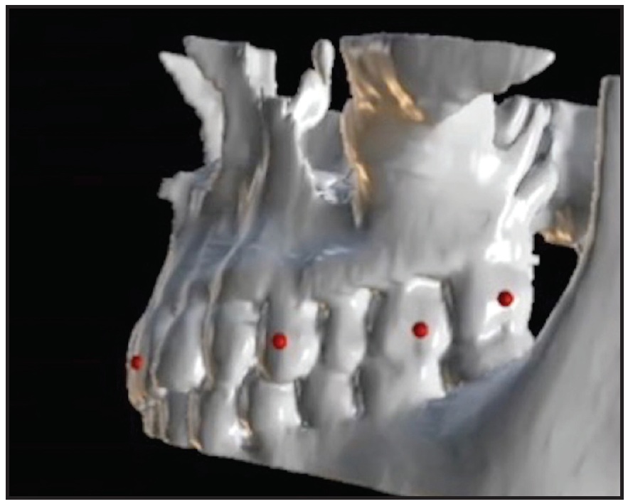
Fig. 1 Three-dimensional superimposition of digital maxillary scan onto cone-beam computed tomographic volume rendering of maxilla.
The “customize implant” function is used to create a virtual miniscrew with an abutment representing the extra-alveolar screw head (Fig. 2). The software requires the following dimensions: screw body length extension (length), screw apical body diameter (apical diameter), screw occlusal body diameter (occlusal diameter), abutment length extension, and abutment diameter. The miniscrew can be considered as a monophasic temporary implant with an infraosseus portion, an inframucosal neck, and an intraoral portion (miniscrew head). The infraosseus portion and gingival neck are part of the screw body; the head of the miniscrew is the abutment. The screw dimensions can be obtained from the manufacturer or by measuring the miniscrew with a digital caliper, and the virtual equivalent can be saved in the software library for future case planning.
The digital miniscrews are virtually placed in the anterior region of the palate, usually at the level of the third palatal ruga.27 The clinician can adjust the position and orientation of the screws in the axial, coronal, and sagittal views as well as in the 3D rendering (Fig. 3). The objective is to ensure adequate bone support and the desired relationship with the nasal cortical bone, avoiding contact with the nasopalatine foramen—the only critical anatomical structure in terms of potential neuronal lesions during insertion. In cases of multiple miniscrew insertions, Blue Sky Plan has a feature that ensures miniscrew parallelism, facilitating insertion of the miniscrew-supported appliance. If a hybrid appliance is being designed, with bands on the maxillary molars, the miniscrew orientation should be adjusted to coordinate the screw insertion path with the band positions.
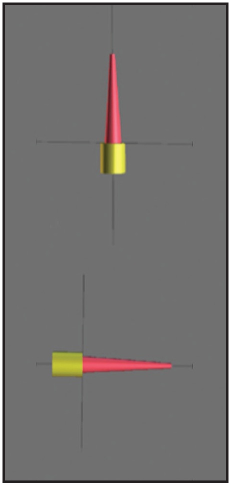
Fig. 2 Digitally designed equivalent of palatal miniscrew (yellow abutment represents miniscrew head).
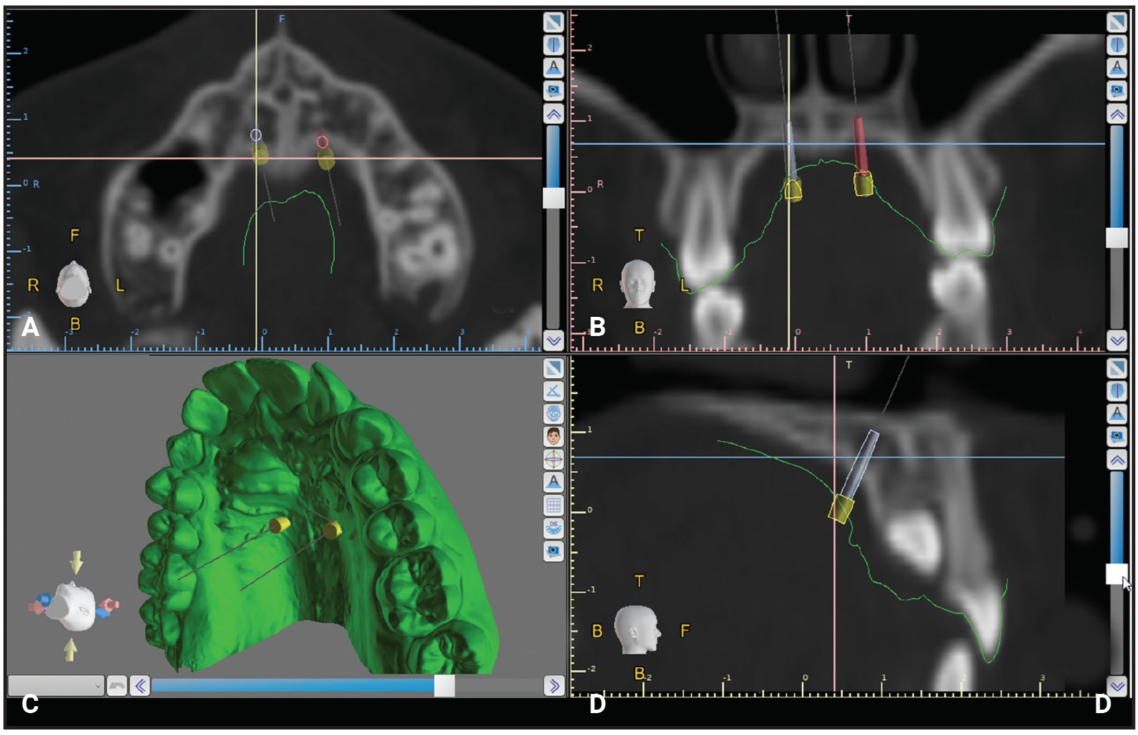
Fig. 3 Virtual planning of miniscrew insertion. A. Axial view. B. Coronal view. C. 3D rendering. D. Sagittal view.
Ideally, the intersection between screw body and head should be at the level of the palatal mucosal surface, so that the screw head is clear of the palatal mucosa. If two parallel miniscrews are planned in the anterior paramedian region, however, the lateral slope of the palatal mucosa could overlap the miniscrews. To avoid patient discomfort, it is important to maintain free space around the miniscrew heads during placement of the impression caps (if a traditional impression is being taken for appliance construction) and during appliance insertion.
The next step is to design a surgical tube, part of the surgical guide that will ensure proper screw orientation during insertion. The software needs three parameters—guide-hole diameter, offset, and height—which can be measured with a digital caliper (Fig. 4A). To obtain the guide-hole diameter, the diameter of the miniscrew pickup driver is measured, and .2mm is added to allow frictionless interaction between pickup and tube. The offset is found by inserting the screw into the pickup driver and measuring the linear extension from the end of the miniscrew neck to the occlusal limit of the pickup. When the offset parameter is correct, the miniscrew will reach its planned vertical position when the occlusal limit of the surgical tube coincides with the occlusal limit of the pickup. To ensure maximum precision during insertion, it is important to extend the guide tube up to the palatal mucosa, which requires the tube height parameter to match the value of the offset parameter.
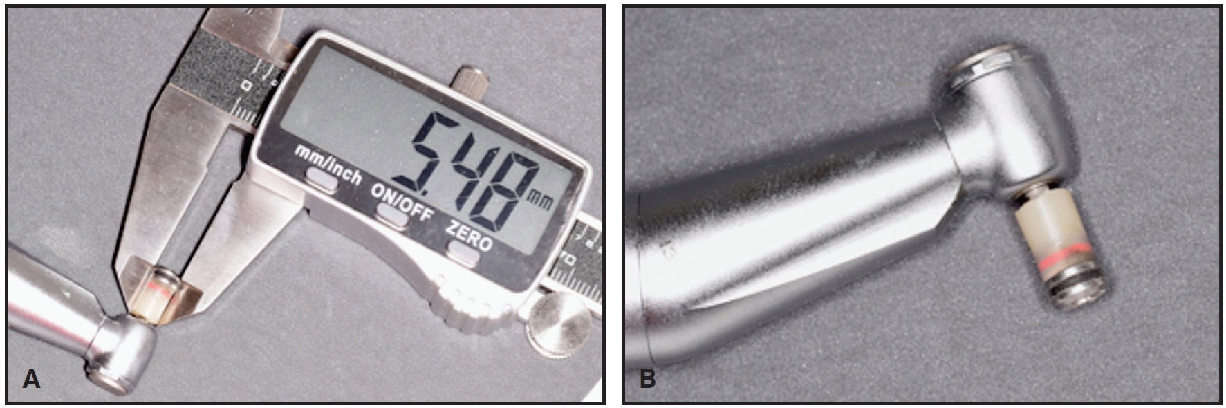
Fig. 4 A. Digital caliper used to record measurements for virtual design of surgical insertion tube. B. Conversion of conventional 10mm OrthoEasy** mechanical pickup into pickup driver for miniscrew insertion.
Once the tube parameters have been entered, the surgical guide is designed to rest on the occlusal surfaces of the posterior teeth (Fig. 5). The dimensions of the surgical guide are defined by tracing its border on the 3D model and subsequently adjusting the selection dots that define the extension curve. The guide must be stable without being excessively bulky, and it should permit good visibility and easy removal once the miniscrews are placed. Therefore, it is essential to extend the anterior and posterior margins of the guide beyond the profile of the surgical tubes—usually to the upper canines and first molars, depending on the individual patient’s characteristics. The most posterior upper molars are not included so as to limit the occlusal extension while still providing good stability. Vertical “windows” can be designed in the anterior or posterior regions of the guide tubes to facilitate miniscrew insertion in patients with limited mouth opening. These windows will also assist the clinician in checking the progress of insertion, which is complete when the upper occlusal margin of the pickup driver reaches the upper margin of the guide-tube window.
The Blue Sky Plan software will automatically complete the design of the surgical guide, removing undercuts for easy insertion. The digital design is than exported as an STL file, which is used for 3D printing of the surgical guide with a resin*** intended for that purpose (Fig. 6).
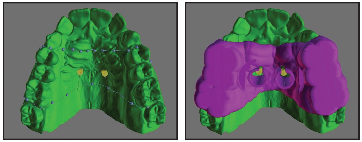
Fig. 5 Digital design of surgical guide.
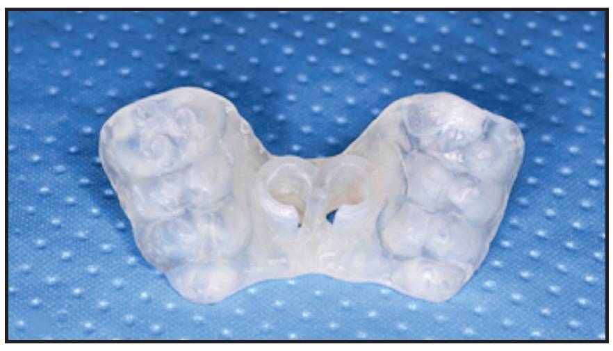
Fig. 6 3D-printed surgical guide.
Case Report
A 15-year-old female sought orthodontic treatment to improve her smile esthetics (Fig. 7A).
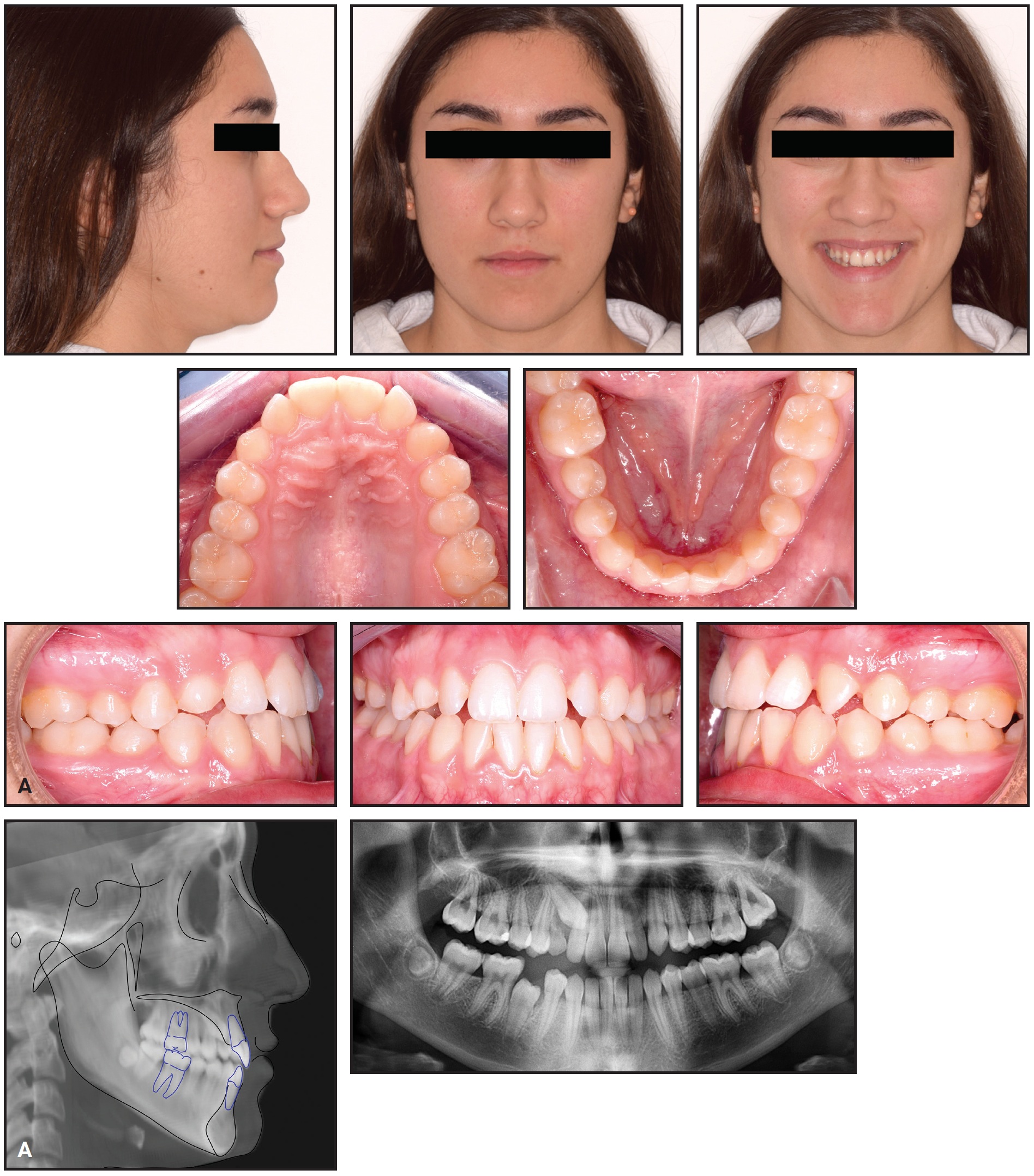
Fig. 7 A. 15-year-old female patient with Class I molar relationship, moderate crowding, and impacted upper right canine before treatment (continued in next image).
She displayed good facial symmetry and lateral buccal corridors on smiling, with a harmonic profile and adequate lip projection. The patient had a Class I molar relationship on both sides and moderate crowding in both arches. Cephalometric analysis confirmed good skeletal proportions in both the sagittal and vertical planes. The panoramic x-ray revealed an impacted upper right canine with mesial crown inclination. A CBCT surface rendering of the segmented maxillary teeth28 showed the canine to be in a palatal position, mesially inclined, with the crown just behind the roots of the lateral and central incisors and the root close to the apex of the first premolar. Analysis of the digital models with Maestro 3D† found excessive buccal crown torque of the upper molars and premolars on both sides, indicating dentoalveolar compensation for maxillary constriction (Fig. 7B).
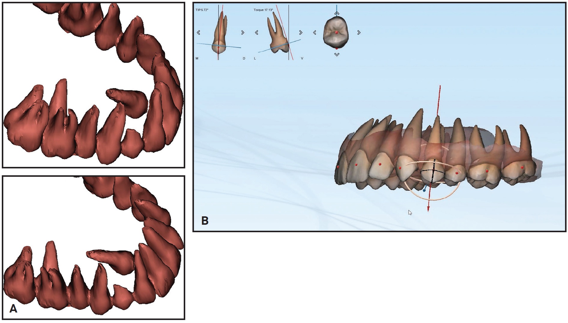
Fig. 7 (cont.) A. 15-year-old female patient with Class I molar relationship, moderate crowding, and impacted upper right canine before treatment. B. Analysis of digital models shows excessive buccal crown torque of upper premolars and molars.
Initial treatment goals included skeletal expansion of the maxillary arch and de-impaction of the upper right canine with maximum anchorage. Considering the patient’s age and dentoalveolar compensation, we decided to use a miniscrew-anchored device for optimal skeletal expansion. Two miniscrews would be inserted in the anterior paramedian region of the palate to support the expander.
CBCT examination was performed using an i-CAT‡ unit with settings of .3 isotropic voxels, 8.9s, 100kV, 20mA, and a small 8cm × 5cm field of view. The distance between two slices was set at .3mm to ensure accuracy in anatomical registration. An intraoral scan was taken using a Medit I500†† and exported as an STL file. The DICOM and STL files were then imported into Blue Sky Plan for registration and superimposition.
Digital equivalents of two self-drilling miniscrews were selected with Blue Sky Plan’s “customize implant” feature. Using the coronal, sagittal, and axial views of the CBCT scans, the miniscrew orientation and insertion site were adjusted to obtain an area with adequate bone and to maintain a safe distance from the impacted canine. Adjustments were also made in the 3D view to verify proper inclination of the miniscrews in relation to the main axes of the first molars,29 as well as full coverage of the transmucosal miniscrew neck and free space between the miniscrew heads and the lateral slope of the palatal mucosa. Next, the surgical guide was digitally designed and 3D-printed*** as described above.
After local anesthesia (2% lidocaine) was administered in the surgical sites, the surgical guide was fitted to the occlusal surfaces of the posterior teeth. Two OrthoEasy Pal** miniscrews were inserted into the adapted pickup driver and mounted on a contra-angle handpiece at a low speed of 40rpm (Fig. 8). The cylindrical guide tubes were designed according to the dimensions of the pickup driver to ensure that the screws were inserted at the correct angle and the planned depth (Fig. 9).
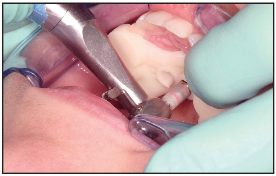
Fig. 8 Insertion of OrthoEasy Pal** miniscrew using surgical guide.
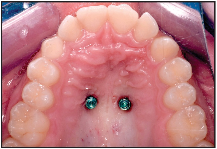
Fig. 9 Two parallel miniscrews after insertion in anterior palate.
After impression transfer copings were placed over the miniscrew heads, a precision impression was taken with vinyl polysiloxane, and the miniscrew positions were replicated with two analogs (Fig. 10). A hybrid Hyrax‡‡ expander was fabricated with an anterior arm on the right side and an attached eyelet that would serve as an occlusal guide for traction of the impacted canine (Fig. 11). The arm was designed to generate a force vector capable of moving the canine crown distally and occlusally, thus facilitating guided eruption.
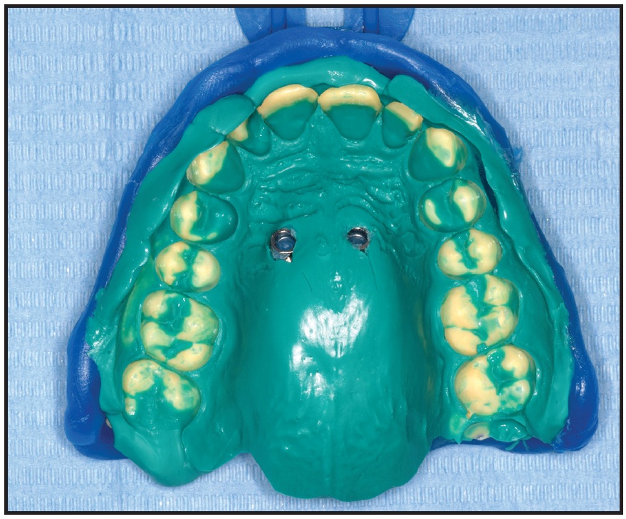
Fig. 10 Vinyl polysiloxane impression with two miniscrew analogs.
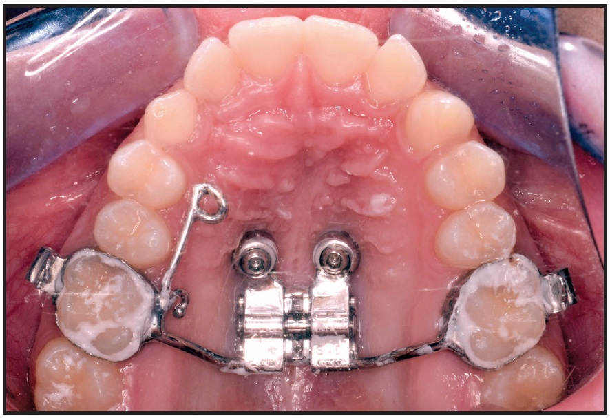
Fig. 11 Hybrid Hyrax‡‡ expander with right anterior arm for traction of impacted canine and eyelet for eruption guidance.
To achieve rapid maxillary expansion, the jackscrew was activated with a .25mm turn twice a day (.5mm per day) for 13 days, obtaining a total screw activation of 3.5mm per side. Activations were discontinued once dental overexpansion was achieved, with the mesiopalatal cusps of the upper first molars in contact with the buccal cusps of the lower first molars. A diastema appeared between the upper central incisors, confirming skeletal opening of the midpalatal suture, but a scissor bite developed in the posterior segments (Fig. 12).
After three months of passive retention, the impacted canine was surgically exposed (Fig. 13A). An eyelet was bonded to the palatal surface of the canine, and force was generated by tying a metallic ligature wire between this eyelet and the eyelet on the palatal arm (Fig. 13B). A composite ball was bonded to the distal end of the ligature wire, and an elastomeric chain was attached between the composite ball and a metal hook welded to the arm of the expander. The elastomeric chain generated sufficient force for guided eruption of the impacted canine through the palatal mucosa.
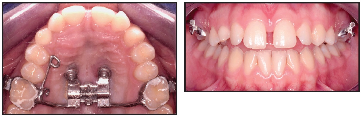
Fig. 12 Diastema between upper central incisors after 13 days of jackscrew activation.
The patient was seen every two weeks to check treatment progress and change the elastomeric chain. After three months, the crown of the permanent canine was clearly visible in the area adjacent to the deciduous canine. The palatal arm was removed, and the boneborne Hyrax expander was kept in place to be activated for spontaneous dental decompensation (Fig. 14).
Although the patient needed subsequent treatment with fixed appliances, this preliminary phase of skeletally anchored expansion and canine eruption transformed a complex case into a simpler one.
Discussion
Skeletal anchorage is seeing widespread use among clinicians because it facilitates complex orthodontic biomechanics that can overcome the limitations of conventional treatment with fixed appliances.9 Bone-supported anchorage makes it possible to increase the efficacy of orthodontic tooth movements, counteracting undesired dental side effects while enhancing orthopedic effects.1,9
Although surgical guides have been recommended for precise miniscrew placement in relation to the cortical nasal bone,5,30,31 a miniscrew can be successfully placed in the anterior palatal region even without a surgical guide.32-34 A palatal insertion site is relatively secure because of the availability of bone and the absence of anatomical structures such as nerves and important blood vessels.27,35 A lateral cephalogram can provide a reliable evaluation of vertical palatal bone thickness as far as 5mm from the median palatine raphe.36 Even so, the presence of impacted or palatally ectopic teeth is a good indication for the use of a digitally assisted miniscrew insertion system in the anterior palatal region, considering that contact with dental elements is a major cause of miniscrew failure.37
A digitally assisted miniscrew insertion system offers several advantages: it ensures reliable and accurate miniscrew placement, avoiding contact with the roots; it allows the clinician to control miniscrew inclination and parallelism, facilitating orthodontic appliance placement and preventing bone trauma during insertion; and it enables more precise planning of the relationship between the miniscrew and the cortical palatal and nasal bone. Disadvantages include the need for CBCT evaluation, with its additional radiation exposure. In the case shown here, however, the impacted canine itself would have been sufficient indication for CBCT.38,39 The cost per case may be slightly higher in terms of clinical and laboratory time, but the Blue Sky Plan software is free. While many companies offer digital systems for guided insertion of their own miniscrews, an open system adaptable to all available miniscrews offers a distinct workflow advantage. This application could not only reduce costs, but could also improve communication between the clinician and the laboratory, who can share projects using cloud-based files on the same software platform.
FOOTNOTES
- *Registered trademark of Blue Sky Bio, LLC, Grayslake, IL; www.blueskybio.com.
- **Registered trademark of Forestadent GmbH, Pforzheim, Germany; www.forestadent.com.
- ***Formlabs, Inc., Somerville, MA; www.formlabs.com.
- †Registered trademark of AGE Solutions S.r.l., Pisa, Italy; www.maestro3d.com.
- ‡Registered trademark of Imaging Sciences International, Hatfield, PA; www.i-cat.com.
- ††Registered trademark of Medit Corp., Seoul, South Korea; www.medit.com.
- ‡‡Registered trademark of Dentaurum, Inc., Newtown, PA; www.dentaurum.com.
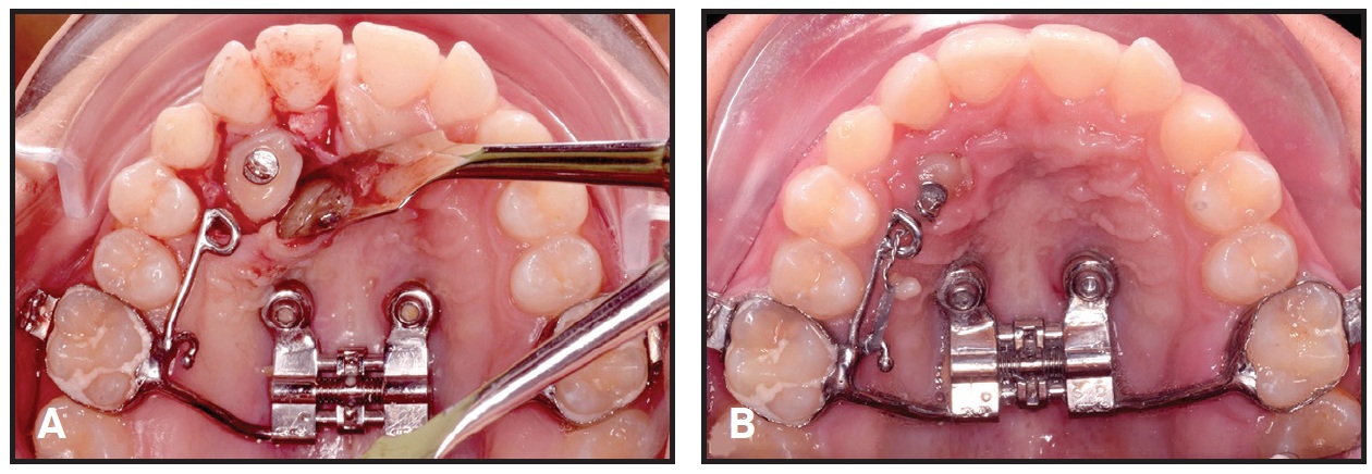
Fig. 13 A. Surgical exposure of impacted upper right canine after three months of passive retention. B. Eyelet bonded to palatal surface of impacted canine for traction by metallic ligature wire and elastomeric chain.
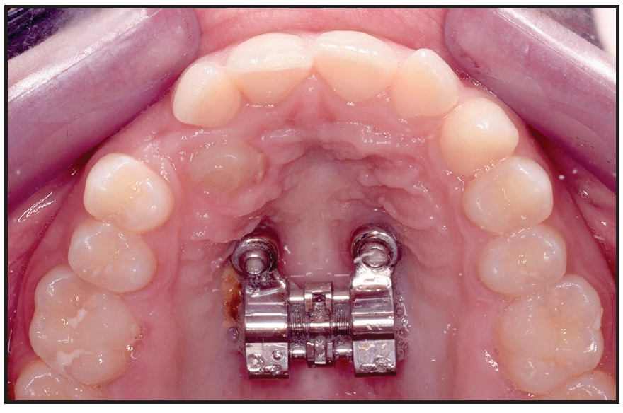
Fig. 14 Hyrax expander kept in placed as boneborne retention appliance for spontaneous dental decompensation.
REFERENCES
- 1. Jones, J.P.; Elnagar, M.H.; and Perez, D.E.: Temporary skeletal anchorage techniques, Oral Maxillofac. Surg. Clin. 32:27-37, 2020.
- 2. Saga, A.Y.; Araújo, E.A.; Antelo, O.M.; Meira, T.M.; and Tanaka, O.M.: Nonsurgical treatment of skeletal maxillary protrusion with gummy smile using headgear for growth control, mini-implants as anchorage for maxillary incisor intrusion, and premolar extractions for incisor retraction, Am. J. Orthod. 157:245-258, 2020.
- 3. Krüsi, M.; Eliades, T.; and Papageorgiou, S.N.: Are there benefits from using bone-borne maxillary expansion instead of tooth-borne maxillary expansion? A systematic review with meta-analysis, Prog. Orthod. 20:9, 2019.
- 4. Lo Giudice, A.; Quinzi, V.; Ronsivalle, V.; Martina, S.; Bennici, O.; and Isola, G.: Description of a digital work-flow for CBCT-guided construction of micro-implant supported maxillary skeletal expander, Mater. (Basel) 13:1815, 2020.
- 5. Maino, B.G.; Paoletto, E.; Lombardo, L. III; and Siciliani, G.: A three-dimensional digital insertion guide for palatal miniscrew placement, J. Clin. Orthod. 50:12-22, 2016.
- 6. Baumgaertel, S. and Hans, M.G.: Assessment of infrazygomatic bone depth for mini-screw insertion, Clin. Oral Implants Res. 20:638-642, 2009.
- 7. Liou, E.J.; Chen, P.H.; Wang, Y.C.; and Lin, J.C.: A computed tomographic image study on the thickness of the infrazygomatic crest of the maxilla and its clinical implications for miniscrew insertion, Am. J. Orthod. 131:352-356, 2007.
- 8. Nucera, R.; Bellocchio, A.M.; Oteri, G.; Farah, A.J.; Rosalia, L.; Giancarlo, C.; and Portelli, M.: Bone and cortical bone characteristics of mandibular retromolar trigone and anterior ramus region for miniscrew insertion in adults, Am. J. Orthod. 155:330-338, 2019.
- 9. Nucera, R.; Lo Giudice, A.; Bellocchio, A.M.; Spinuzza, P.; Caprioglio, A.; Perillo, L.; Matarese, G.; and Cordasco, G.: Bone and cortical bone thickness of mandibular buccal shelf for mini-screw insertion in adults, Angle Orthod. 87:745-751, 2017.
- 10. Chhatwani, S.; Rose-Zierau, V.; Haddad, B.; Almuzian, M.; Kirschneck, C.; and Danesh, G.: Three-dimensional quantitative assessment of palatal bone height for insertion of orthodontic implants—a retrospective CBCT study, Head Face Med. 15:9, 2019.
- 11. Hourfar, J.; Bister, D.; Kanavakis, G.; Lisson, J.A.; and Ludwig, B.: Influence of interradicular and palatal placement of orthodontic mini-implants on the success (survival) rate, Head Face Med. 13:14, 2017.
- 12. Gracco, A.; Lombardo, L.; Cozzani, M.; and Siciliani, G.: Quantitative cone-beam computed tomography evaluation of palatal bone thickness for orthodontic miniscrew placement, Am. J. Orthod. 134:361-369, 2008.
- 13. Holm, M.; Jost-Brinkmann, P.G.; Mah, J.; and Bumann, A.: Bone thickness of the anterior palate for orthodontic miniscrews, Angle Orthod. 86:826-831, 2016.
- 14. Leonardi, R.; Lo Giudice, A.; Rugeri, M.; Muraglie, S.; Cordasco, G.; and Barbato, E.: Three-dimensional evaluation on digital casts of maxillary palatal size and morphology in patients with functional posterior crossbite, Eur. J. Orthod. 40:556-562, 2018.
- 15. Marquezan, M.; Nojima, L.I.; Freitas, A.O.; Baratieri, C.; Alves Júnior, M.; Nojima, M.C.G.; and Araújo, M.T.S.: Tomographic mapping of the hard palate and overlying mucosa, Braz. Oral Res. 26:36-42, 2012.
- 16. Ludwig, B.; Glasl, B.; Bowman, S.J.; Wilmes, B.; Kinzinger, G.S.; and Lisson, J.A.: Anatomical guidelines for miniscrew insertion: Palatal sites, J. Clin. Orthod. 45:433-441, 2011.
- 17. Scarfe, W.C.; Farman, A.G.; and Sukovic, P.: Clinical applications of cone-beam computed tomography in dental practice, J. Can. Dent. Assoc. 72:75-80, 2006.
- 18. Guerrero, M.E.; Jacobs, R.; Loubele, M.; Schutyser, F.; Suetens, P.; and Van Steenberghe, D.: State-of-the-art on cone beam CT imaging for preoperative planning of implant placement, Clin. Oral Investig. 10:1-7, 2006.
- 19. Leonardi, R.: Cone-beam computed tomography and three-dimensional orthodontics: Where we are and future perspectives, J. Orthod. 46:45-48, 2019.
- 20. Colceriu-Şimon, I.M.; Băciuţ, M.; Ştiufiuc, R.I.; Aghiorghiesei, A.; Ţărmure, V.; Lenghel, M.; Hedeşiu, M.; and Băciuţ, G.: Clinical indications and radiation doses of cone beam computed tomography in orthodontics, Med. Pharm. Rep. 92:346-351, 2019.
- 21. Matarese, G.; Portelli, M.; Mazza, M.; Militi, A.; Nucera, R.; Gatto, E.; and Cordasco, G.: Evaluation of skin dose in a low dose spiral CT protocol, Eur. J. Paediat. Dent. 7:77-80, 2006.
- 22. Cordasco, G.; Portelli, M.; Militi, A.; Nucera, R.; Lo Giudice, A.; Gatto, E.; and Lucchese, A.: Low-dose protocol of the spiral CT in orthodontics: Comparative evaluation of entrance skin dose with traditional x-ray techniques, Prog. Orthod. 14:24, 2013.
- 23. Brunetto, D.P.; Sant’Anna, E.F.; Machado, A.W.; and Moon, W.: Non-surgical treatment of transverse deficiency in adults using microimplant-assisted rapid palatal expansion (MARPE), Dent. Press J. Orthod. 22:110-125, 2017.
- 24. Cantarella, D.; Savio, G.; Grigolato, L.; Zanata, P.; Berveglieri, C.; Lo Giudice, A.; Isola, G.; Del Fabbro, M.; and Moon, W.: A new methodology for the digital planning of micro-implant-supported maxillary skeletal expansion, Med. Dev. (Auckl.) 13:93-106, 2020.
- 25. Portelli, M.; Militi, A.; Lo Giudice, A.; Lo Giudice, R.; Fastuca, R.; Ielo, I.; Mongelli, V.; Lo Giudice, G.; Martintoni, A.; Manuelli, M.; Lucchese, A.; and Nucera, R.: Standard and low-dose cone beam computed tomography protocol for orthognatodontic diagnosis: A comparative evaluation, J. Biol. Regul. Homeost. Agents 32:59-66, 2018.
- 26. Loubele, M.; Bogaerts, R.; Van Dijck, E.; Pauwels, R.; Vanheusden, S.; Suetens, P.; Marchal, G.; Sanderink, G.; and Jacobs, R.: Comparison between effective radiation dose of CBCT and MSCT scanners for dentomaxillofacial applications, Eur. J. Radiol. 71:461-468, 2009.
- 27. Hourfar, J.; Kanavakis, G.; Bister, D.; Schätzle, M.; Awad, L.; Nienkemper, M.; Goldbecher, C.; and Ludwig, B.: Three dimensional anatomical exploration of the anterior hard palate at the level of the third ruga for the placement of mini-implants—a cone-beam CT study, Eur. J. Orthod. 37:589-595, 2015.
- 28. Leonardi, R.; Muraglie, S.; Crimi, S.; Pirroni, M.; Musumeci, G.; and Perrotta, R.: Morphology of palatally displaced canines and adjacent teeth, a 3-D evaluation from cone-beam computed tomographic images, BMC Oral Health 18:156, 2018.
- 29. Maino, B.G.; Maino, G.; and Mura, P.: Spider Screw: Skeletal anchorage system, Prog. Orthod. 6:70-81, 2005.
- 30. Cassetta, M.; Altieri, F.; Di Giorgio, R.; and Barbato, E.: Palatal orthodontic miniscrew insertion using a CAD-CAM surgical guide: Description of a technique, Int. J. Oral Maxillofac. Surg. 47:1195-1198, 2018.
- 31. Suzuki, E.Y. and Suzuki, B.: Accuracy of miniscrew implant placement with a 3-dimensional surgical guide, J. Oral Maxillofac. Surg. 66:1245-1252, 2008.
- 32. Kakali, L.; Alharbi, M.; Pandis, N.; Gkantidis, N.; and Kloukos, D.: Success of palatal implants or mini-screws placed median or paramedian for the reinforcement of anchorage during orthodontic treatment: A systematic review, Eur. J. Orthod. 41:9-20, 2019.
- 33. Mohammed, H.; Wafaie, K.; Rizk, M.Z.; Almuzian, M.; Sosly, R.; and Bearn, D.R.: Role of anatomical sites and correlated risk factors on the survival of orthodontic miniscrew implants: A systematic review and meta-analysis, Prog. Orthod. 19:36, 2018.
- 34. Möhlhenrich, S.C.; Brandt, M.; Kniha, K.; Prescher, A.; Hölzle, F.; Modabber, A.; Wolf, M.; and Peters, F.: Accuracy of orthodontic mini-implants placed at the anterior palate by tooth-borne or gingiva-borne guide support: A cadaveric study, Clin. Oral Investig. 23:4425-4431, 2019.
- 35. Baumgaertel, S.: Quantitative investigation of palatal bone depth and cortical bone thickness for mini-implant placement in adults, Am. J. Orthod. 136:104-108, 2009.
- 36. Kim, Y.J.; Lim, S.H.; and Gang, S.N.: Comparison of cephalometric measurements and cone-beam computed tomography-based measurements of palatal bone thickness, Am. J. Orthod. 145:165-172, 2014.
- 37. Kuroda, S.; Yamada, K.; Deguchi, T.; Hashimoto, T.; Kyung, H.M.; and Takano-Yamamoto, T.: Root proximity is a major factor for screw failure in orthodontic anchorage, Am. J. Orthod. 131:S68-S73, 2007.
- 38. Portelli, M.; Nucera, R.; Fastuca, R.; Cicciù, M.; Lo Giudice, A.; and Militi, A.: Use of 3D imaging for treatment planning in cases of impacted canines, Open Dent. J. 13:137-142, 2019.
- 39. Hodges, R.J.; Atchison, K.A.; and White, S.C.: Impact of cone-beam computed tomography on orthodontic diagnosis and treatment planning, Am. J. Orthod. 143:665-674, 2013.
-
 DR. LO GIUDICE
 -
 DR. RUSTICO
 -
 DR. CAMPAGNA
 -
 DR. PORTELLI
 -
 DR. NUCERA
Dr. Lo Giudice is an Adjunct Professor, Department of Orthodontics, School of Dentistry, Vittorio Emanuele University Hospital, University of Catania, Via S. Sofia 78, 95123 Catania, Italy; e-mail: nino.logiudice@gmail.com. Dr. Rustico is in the private practice of orthodontics in Ispica, Italy. Dr. Campagna in the private practice of orthodontics in Catania, Italy. Dr. Portelli is an Assistant Professor and Dr. Nucera is an Associate Professor, Department of Orthodontics, School of Dentistry, University of Messina, Messina, Italy.