THE CUTTING EDGE
CAD/CAM Technology for Digital Indirect Bonding
This column is compiled by JCO Technology Editor Marc S. Lemchen, DMD. To help keep our readers on The Cutting Edge, Dr. Lemchen will spotlight a particular area of orthodontic technology every few months. Your suggestions for future subjects or authors are welcome.
As practicing orthodontists, we often become comfortable with the techniques and procedures we have used for many years. This is equally true of our staff members. While I try to remember that for the most part “change is positive,” the introduction of any new procedure requires training the orthodontic team and changing the workflow in the office. No matter how much of an improvement it may be over the old way, it takes more time in the beginning, and our initial impression is that we just don’t have time for it, at least not today.
Indirect bonding has always required a commitment beyond sitting down and placing brackets directly on the patient’s teeth. (We may even remember the difficulty of learning bonding techniques as opposed to fitting and cementing bands. Who would go back to that now?) At first, indirect bonding required extra appointments, delaying case starts, and introduced new opportunities for failure, especially as we were learning our way. Once mastered, however, indirect bonding can be faster and more accurate—a better patient experience with better treatment outcomes.
Now, as we enter the digital age, we can produce indirect-bonding trays in our offices using three-dimensional printers. Once again, this requires adopting new software and technology—a new procedure with a learning curve. We need to work with and track a digital representation of something we can’t see as a physical model on a desk or in a bin, or as brackets on the model. We work in a virtual world of acquiring stereolithographic (STL) data, transferring the STL data to a laboratory or into specialized software, and verifying that these data were submitted to the lab or person responsible for turning it into a physical reality. Everything is virtual until we hit the print button, and then out comes a model, a splint, or—in the procedure so well documented here—an indirect-bonding tray.
MSL
Similar articles from the archive:
CAD/CAM Technology for Digital Indirect Bonding
Accurate bracket placement is crucial for tooth alignment and efficient orthodontic treatment, especially when using preadjusted appliances.1,2 Repositioning brackets and bending archwires to fix errors are both time-consuming procedures that can lead to longer treatment times.2-4
The indirect bonding technique was first described in 1972.5 Since then, various materials and methods have been used to transfer brackets to the teeth, including hard and soft vacuum-formed sheets, rubber-base impression materials, jigs, and wax guns.6,7 Some studies have reported advantages over direct bonding, such as better visibility during bracket positioning and reduced chairtime.3,4,8 Nevertheless, neither indirect nor direct bonding can ensure ideal bracket positioning.8
Computer-aided design/computer-aided manufacturing (CAD/CAM) technology has been beneficial in other orthodontic procedures, from treatment planning to the fabrication of clear aligners and customized lingual and labial appliances.4,9,10 Studies indicate that the use of CAD/CAM software may enable more accurate bracket placement, thus improving orthodontic treatment efficiency.11
The present article illustrates the application of CAD/CAM technology to digitally position brackets and to design and print transfer trays for indirect bonding.
Case Report
A 13-year-old female presented with the desire to improve her smile (Fig. 1).
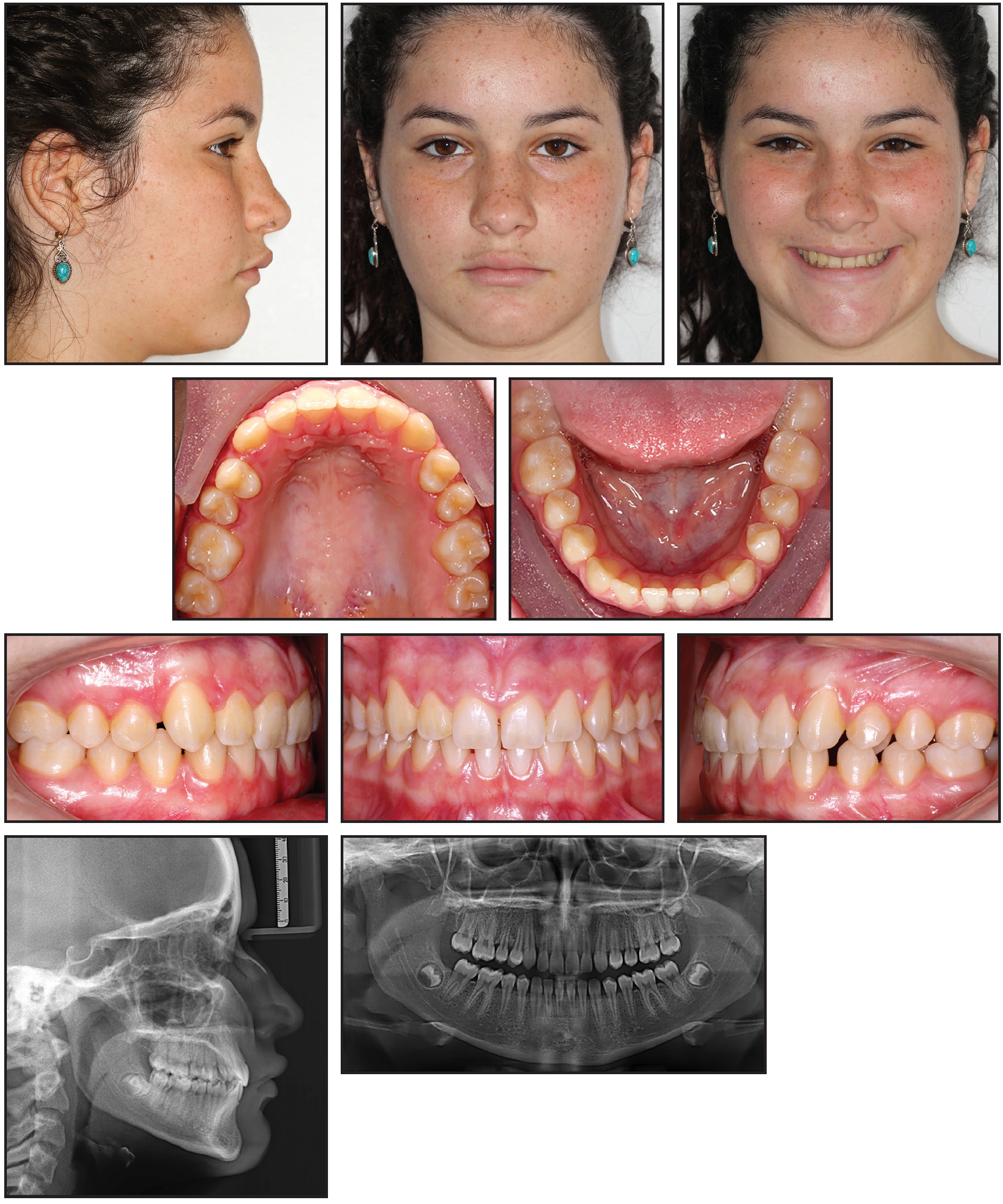
Fig. 1 13-year-old female patient with Class I malocclusion on right side and mild Class II on left, mandibular midline shift, multiple diastemas, and deep overbite before treatment.
Examination revealed a Class I malocclusion on the right side and a mild Class II on the left, a mandibular midline shift, multiple diastemas, and a deep overbite. Orthodontic treatment was planned using digital indirect bonding.
Intraoral scanning of both arches and the bite was completed with a TRIOS* color intraoral scanner, according to the manufacturer’s instructions. After scanning, the models were imported into OrthoAnalyzer** software. Volumetric data from the patient’s cone-beam computed tomography (CBCT) were loaded to the software, and the CBCT and intraoral scan were aligned.
After the virtual base was created (Fig. 2) and occlusal and standard planes were defined, the maxillary and mandibular models were segmented (Fig. 3).12
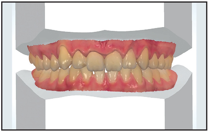
Fig. 2 Virtual model base.

Fig. 3 Segmentation of maxillary model. A. Mesial and distal points established. B. Cut defined. C. Centers of rotation and long axis automatically defined by software** using proximal contacts (clinician can adjust manually). D. CBCT superimposed on intraoral scan.
Next, the facial axis point was adjusted for each tooth, according to the desired bracket positions (Fig. 4).
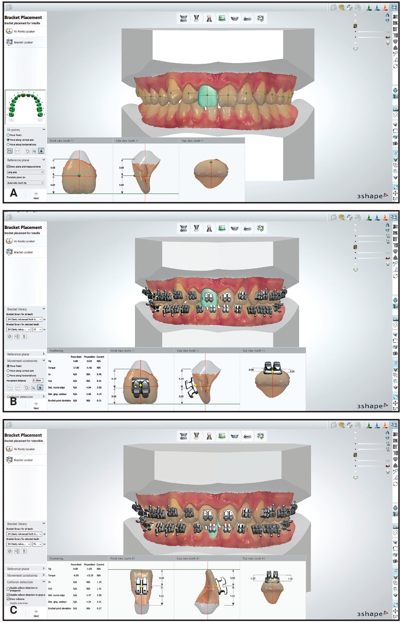
Fig. 4 A. Facial axis points adjusted on virtual model. B. Brackets positioned and adjusted on maxillary arch. C. Brackets positioned and adjusted on mandibular arch.
The bracket selected from the library was the Roth-prescription .022" Clarity Advanced.*** The clinician precisely positioned the brackets in the vertical and horizontal planes and adjusted the axial inclinations, according to the malocclusion and the anatomical shape of the teeth (Fig. 5).
Using Appliance Designer** software (Fig. 6), the transfer trays were prepared to cover only the occlusal half of the brackets and the lingual surfaces of the teeth (Fig. 7).
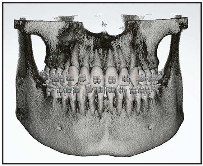
Fig. 5 CBCT with brackets superimposed on intraoral scan.
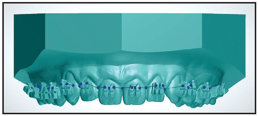
Fig. 6 Design of maxillary transfer tray.
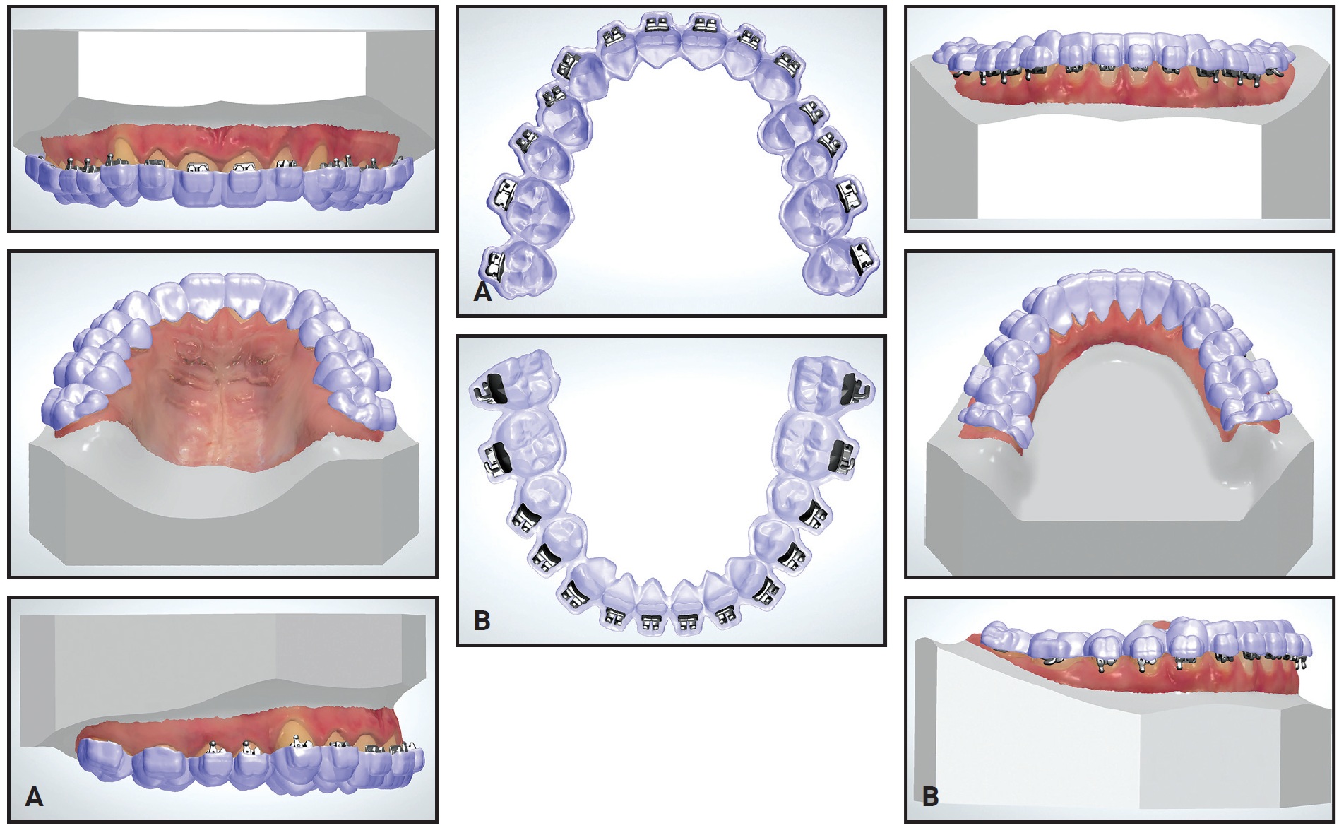
Fig. 7 A. Maxillary transfer tray. B. Mandibular transfer tray.
For correct positioning, the trays must overlap with the teeth. These trays were printed by an outside laboratory† using a 3D printer‡ and materials†† approved by the U.S. Food and Drug Administration.
Prophylaxis was performed on all tooth surfaces. Areas to be bonded were etched with 37% phosphoric acid for 20 seconds, washed, and dried. Adhesive‡‡ was applied according to the manufacturer’s instructions. The actual brackets and tubes were then placed into the transfer trays (Fig. 8). Flow Tain§ flowable light-cured composite was applied to the bracket bases, and the trays were carefully positioned in the mouth. After flash was removed from the cervical regions of the bracket bases, the composite was light-cured using a VALO§§ Ortho LED device (Fig. 9).

Fig. 8 Brackets positioned in transfer tray.
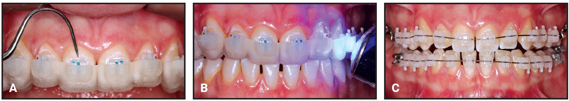
Fig. 9 A. Flash removed from around bracket base with maxillary tray seated. B. Light-curing of composite. C. Bonding completed and archwires inserted.
The trays were removed, and any remaining flash was carefully cleaned away. The bonding procedure took a total 20 minutes of chairtime.
Initial archwires were .014" nickel titanium. Three months later, .018" nickel titanium archwires were placed, followed another month later by .018" stainless steel wires. Class II intermaxillary elastics were started after five months of treatment to correct the anteroposterior discrepancy and to obtain satisfactory interdigitation. After six months of treatment, .017" × .025" stainless steel wires were inserted. All lower archwires had a reverse curve of Spee to further reduce the overbite.
Finishing and detailing took five months. Total treatment time was 13 months (Fig. 10).
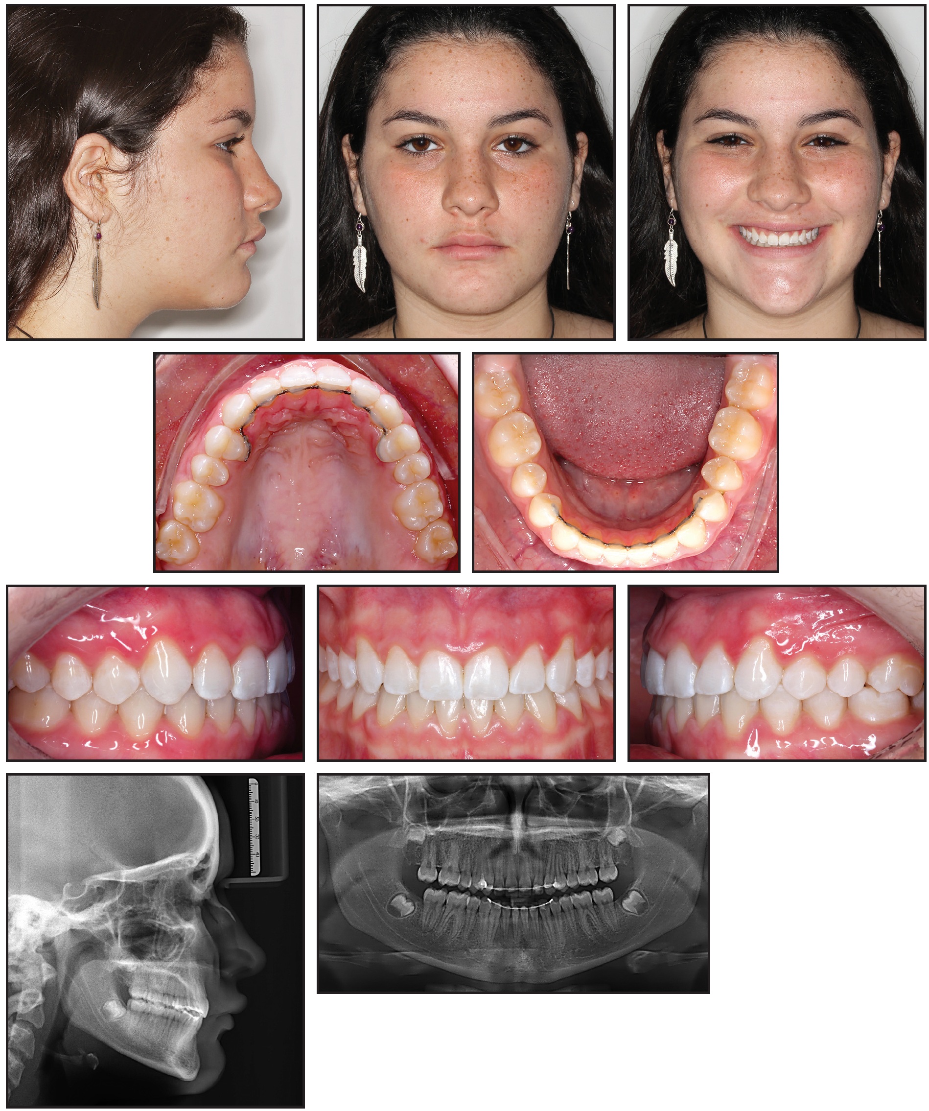
Fig. 10 Patient after 13 months of treatment.
Lingual 4-4 retainers were bonded in both arches.
Discussion
Camardella and colleagues demonstrated the efficacy of digital models produced by the TRIOS intraoral scanner.13 Models do not require physical storage space, and the scans are easily exchanged with other dentists and laboratories.13,14 The procedure is more comfortable for patients, particularly those with a gag reflex. Other common problems with traditional impressions, including air bubbles, deformation, material rupture, and too much or too little impression material, are avoided.13,14 The bracket bases cannot be contaminated with excess adhesive or cast material, and there is no need for time-consuming laboratory procedures.15
To ensure root parallelism at the end of orthodontic treatment, it is critical to consider the long axes of the roots when positioning brackets. If a CBCT image is available, the superimposition of an intraoral digital scan with the CBCT helps improve accuracy in adjusting the brackets’ axial inclinations.15
Although the costs of acquiring the software and using a 3D printer are disadvantages of the indirect-bonding technique shown here, the use of CAD/CAM technology for indirect bonding reduces the laboratory time needed to create the transfer trays and provides greater precision of virtual bracket positioning.13,16
FOOTNOTES
- *Registered trademark of 3Shape, Copenhagen, Denmark; www.3shape.com.
- **Trademark of 3Shape, Copenhagen, Denmark; www.3shape.com.
- ***Trademark of 3M Unitek, Monrovia, CA; www.3Munitek.com.
- †Compass Ortho, Belo Horizonte, Brazil; www.compass3d.com.br.
- ‡Objet Eden500, trademark of Stratasys Ltd., Eden Prairie, MN; www.stratasys.com.
- ††VeroClear, MED610, trademarks of Stratasys Ltd., Eden Prairie, MN; www.stratasys.com.
- ‡‡Single Bond, registered trademark of 3M ESPE Dental Products, St. Paul, MN; www.3m.com.
- §Trademark of Reliance Orthodontics, Inc., Itasca, IL; www.relianceorthodontics.com.
- §§Registered trademark of Ultradent Products, Inc., South Jordan, UT; www.ultradent.com.
REFERENCES
- 1. Andrews, L.F.: The straight-wire appliance, Br. J. Orthod. 6:125-143, 1979.
- 2. Nichols, D.A.; Gardner, G.; and Carballeyra, A.D.: Reproducibility of bracket positioning in the indirect bonding technique, Am. J. Orthod. 144:770-776, 2013.
- 3. Aguirre, M.J.; King, G.J.; and Waldron, J.M.: Assessment of bracket placement and bond strength when comparing direct bonding to indirect bonding techniques, Am. J. Orthod. 82:269-276, 1982.
- 4. Brown, M.W.; Koroluk, L.; Ko, C.C.; Zhang, K.; Chen, M.; and Nguyen, T.: Effectiveness and efficiency of a CAD/CAM orthodontic bracket system, Am. J. Orthod. 148:1067-1074, 2015.
- 5. Silverman, E.; Cohen, M.; Gianelly, A.A.; and Dietz, V.S.: A universal direct bonding system for both metal and plastic brackets, Am. J. Orthod. 62:236-244, 1972.
- 6. Castilla, A.E.; Crowe, J.J.; Moses, J.R.; Wang, M.; Ferracane, J.L.; and Covell, D.A. Jr.: Measurement and comparison of bracket transfer accuracy of five indirect bonding techniques, Angle Orthod. 84:607-614, 2014.
- 7. El Nigoumi, A.: Assessing the accuracy of indirect bonding with 3D scanning technology, J. Clin. Orthod. 50:613-619, 2016.
- 8. Koo, B.C.; Chung, C.H.; and Vanarsdall, R.L.: Comparison of the accuracy of bracket placement between direct and indirect bonding techniques, Am. J. Orthod. 116:346-351, 1999.
- 9. Alford, T.J.; Roberts, W.E.; Hartsfield, J.K.; Eckert, G.J.; and Snyder, R.J.: Clinical outcomes for patients finished with the SureSmile method compared with conventional fixed orthodontic therapy, Angle Orthod. 81:383-388, 2011.
- 10. Weber, D.J.; Koroluk, L.D.; Phillips, C.; Nguyen, T.; and Proffit, W.R.: Clinical effectiveness and efficiency of customized vs. conventional preadjusted bracket systems, J. Clin. Orthod. 47:261-266, 2013.
- 11. Ciuffolo, F.; Epifania, E.; Duranti, G.; De Luca, V.; Raviglia, D.; Rezza, S.; and Festa, F.: Rapid prototyping: A new method of preparing trays for indirect bonding, Am. J. Orthod. 129:75-77, 2006.
- 12. Kravitz, N.D.; Groth, C.; and Shannon, T.: CAD/CAM software for three-dimensional printing, J. Clin. Orthod. 52:22-27, 2018.
- 13. Camardella, L.T.; Breuning, H.; and de Vasconcellos Vilella, O.: Accuracy and reproducibility of measurements on plaster models and digital models created using an intraoral scanner, J. Orofac. Orthop. 78:211-220, 2017.
- 14. Cuperus, A.M.; Harms, M.C.; Rangel, F.A.; Bronkhorst, E.M.; Schols, J.G.; and Breuning, K.H.: Dental models made with an intraoral scanner: A validation study, Am. J. Orthod. 142:308-313, 2012.
- 15. El-Timamy, A.M.; El-Sharaby, F.A.; Eid, F.H.; and Mostafa, Y.A.: Three-dimensional imaging for indirect-direct bonding, Am. J. Orthod. 149:928-931, 2016.
- 16. Groth, C.; Kravitz, N.D.; and Shirck, J.M.: Incorporating three-dimensional printing in orthodontics, J. Clin. Orthod. 52:28-33, 2018.
-
 DR. SPITZ
 -
 DR. GRIBEL
 -
 DR. MARASSI
Dr. Spitz is a doctoral student, Department of Orthodontics, Universidade Federal do Rio de Janeiro, Rio de Janeiro, Brazil. Dr. Gribel is Head of the Department of Digital Dentistry, Pontifical Catholic University of Minas Gerais, Belo Horizonte, Brazil, and in the private practice of orthodontics in Belo Horizonte. Dr. Marassi is in the private practice of orthodontics at Marassi Ortodontia, Av. Americas 8585/523, Rio de Janeiro, 22793081 Brazil; e-mail: marassi@me.com.