Biomechanics of Lower Second-Molar Protraction Using a New Appliance
The technique of using absolute anchorage from endosseous implants for protraction of lower molars was introduced by Roberts and colleagues.1 Since the development of mini-implants, many more clinicians have considered this procedure.2 Although mini-implants do provide absolute anchorage, orthodontic treatment takes longer, with a range of two to four years.3 The increased duration could be due to the time required to correct side effects that tend to occur during molar protraction, such as mesial tipping or mesial-in rotation of the molars and flaring of the incisors.4 These side effects and potential roundtripping can be avoided by understanding the biomechanical variables affecting molar protraction.
In a finite-element study, Nihara and colleagues evaluated the quality of lower-molar movement according to biomechanical variables including the length of the power arm, height of the miniscrew, buccal line of force application, and buccolingual line of force application.5 These authors did not use an archwire during the simulated molar protraction, however, and therefore could not analyze the effects of friction during sliding mechanics, archwire dimensions, archwire deflection, interbracket distance, or the bending moment of the cantilever arm.
The present article will provide a theoretical biomechanical understanding of lower-molar protraction and how it can be designed to avoid roundtripping. We will also introduce a lower-molar protraction appliance and the biomechanical rationale for its use.
Similar articles from the archive:
Biomechanics
In terms of space-closure mechanics, molar protraction is similar to canine retraction: the primary biomechanical considerations relate to the anteroposterior translatory displacement of teeth. Although the mechanics of canine retraction have been described in depth, molar-protraction mechanics with mini-implant anchorage lack a similar level of analysis.6-8 The role of friction during sliding and deflection of the archwire are two important concepts that need to be understood to plan efficient and effective space closure. Additionally, the dynamic interplay among the force applied (F), moment of a force (Mf), and moment of a couple (Mc) determine the nature of tooth movement, at least theoretically.
Frictional forces during sliding mechanics can make the force system unpredictable, but this friction can be controlled or minimized by making some adjustments. Frictional resistance is directly proportional to the force applied, the distance between the point of force application and the center of resistance (CR), and the frictional coefficient; it is inversely related to the width of the molar tube. Therefore, applying optimal force levels closer to the CR and using wider brackets can reduce frictional resistance during molar protraction.9,10
In the initial phase of protraction, the application of an elastic force from a mini-implant to the molar will generate an Mf as the force is applied above the CR of the molar (Fig. 1A). With Mf occurring in a clockwise direction, the molar tips mesially in an uncontrolled manner due to the play between archwire and molar tube. As the molar tips further, the archwire contacts the molar-tube edges, generating an intrabracket Mc (Fig. 1B).
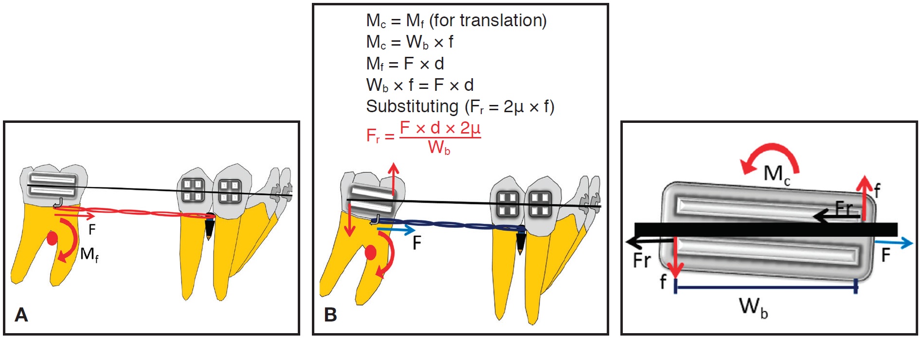
Fig. 1 Biomechanics of molar protraction. A. Force (F) application at molar tube generates clockwise moment of force (Mf) on molar. B. As molar tips mesially, archwire contacts molar-tube edge, creating moment of couple (Mc) that uprights mesially tipped molar with decay of applied force (Wb = bracket width; Fr = frictional resistance; d = perpendicular distance from point of force application to CR of molar; f = intra-bracket couple).
The direction of Mc is opposite to that of Mf, but because Mf is greater than Mc at this stage, the tooth will tip mesially in a controlled manner. With mesial displacement of the molar, the force will decrease in magnitude, due either to decay or relaxation of the applied force, thus reducing Mf. In this phase, when Mc is equal to Mf, the tooth will translate. Later, when Mc is greater than Mf, a significant amount of frictional resistance (primarily due to binding of the archwire to the bracket slots) is generated at the wire-tube interface. This causes the center of rotation to move occlusally between the molar tube and CR, resulting in root uprighting of the molar.9,11
Another important biomechanical component is the deflection of the archwire during sliding mechanics (Fig. 2). This deflection is directly proportional to the cube of the distance between the brackets and inversely proportional to the modulus of elasticity and moment of inertia of the beam (archwire dimensions). Archwire deflection can be minimized by using a stainless steel archwire, but the interbracket span is critical during molar protraction. Any increase in distance can cause considerable deflection during sliding, increasing frictional resistance due to binding.10
We designed a lower-molar protraction appliance to overcome these problems.
Appliance Design
Each molar band has .036" buccal and lingual tubes, 4-5mm wide (Fig. 3).
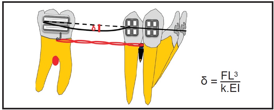
Fig. 2 Deflection of archwire (δ) during molar protraction (L = interbracket span; E = Young’s modulus; I = moment of inertia of beam; k = constant).
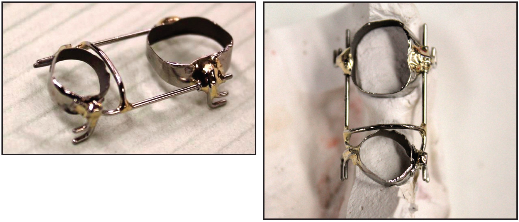
Fig. 3 Lower-molar protraction appliance.
An .032" stainless steel wire is inserted in the tubes on each side and soldered anteriorly to the second-premolar band. Hooks are soldered close to the CR of the molar and premolar for application of elastomeric chain. The premolar band has a slot soldered buccally to engage an .021" × .025" rigid wire for indirect anchorage from a mini-implant between the lower premolars.
The appliance is cemented in place, and a rigid stainless steel power arm is bent from the buccal mini-implant, engaged in the premolar tube, and cinched. The stainless steel segment is splinted over the mini-implant using flowable composite. After stabilization of the appliance, 75g of force is applied on each side with elastomeric chain. The appliance is reactivated every six to eight weeks.
The buccal and lingual .032" stainless steel wires increase the rigidity of the appliance and thus prevent archwire deflection during sliding. Simultaneous buccal and lingual force application helps reduce 1st-order frictional resistance. Because the power arm extends close to the CR of the molar, the point of force application is near the CR, which minimizes mesial tipping of the molar.
Case Report
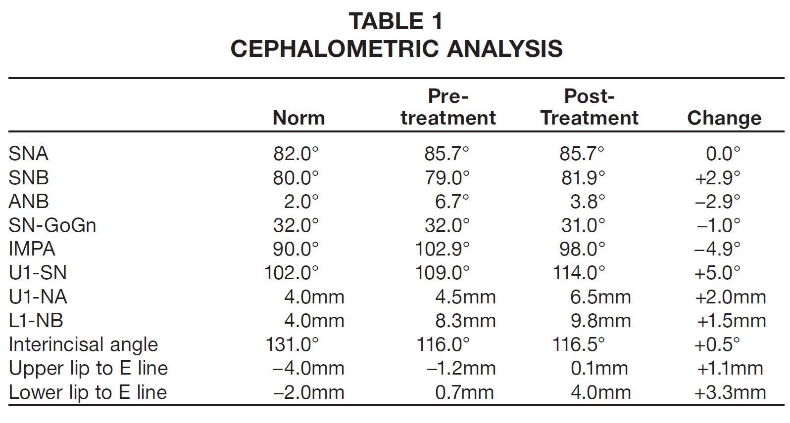
An 11-year-old female reported to the university clinic with the chief complaint of a missing upper front tooth (Fig. 4). Clinical examination showed an orthognathic profile and a well-proportioned face. The upper right central incisor and lower left first molar were missing. The patient had a Class I molar relationship on the right side and end-on Class II buccal segments on the left, with 4-5mm of overjet. The panoramic radiograph revealed an impacted upper right central incisor and mesial tipping of the lower left second molar into the missing first-molar space. Cephalometric analysis indicated a Class II skeletal base with bimaxillary dentoalveolar protrusion (Table 1).
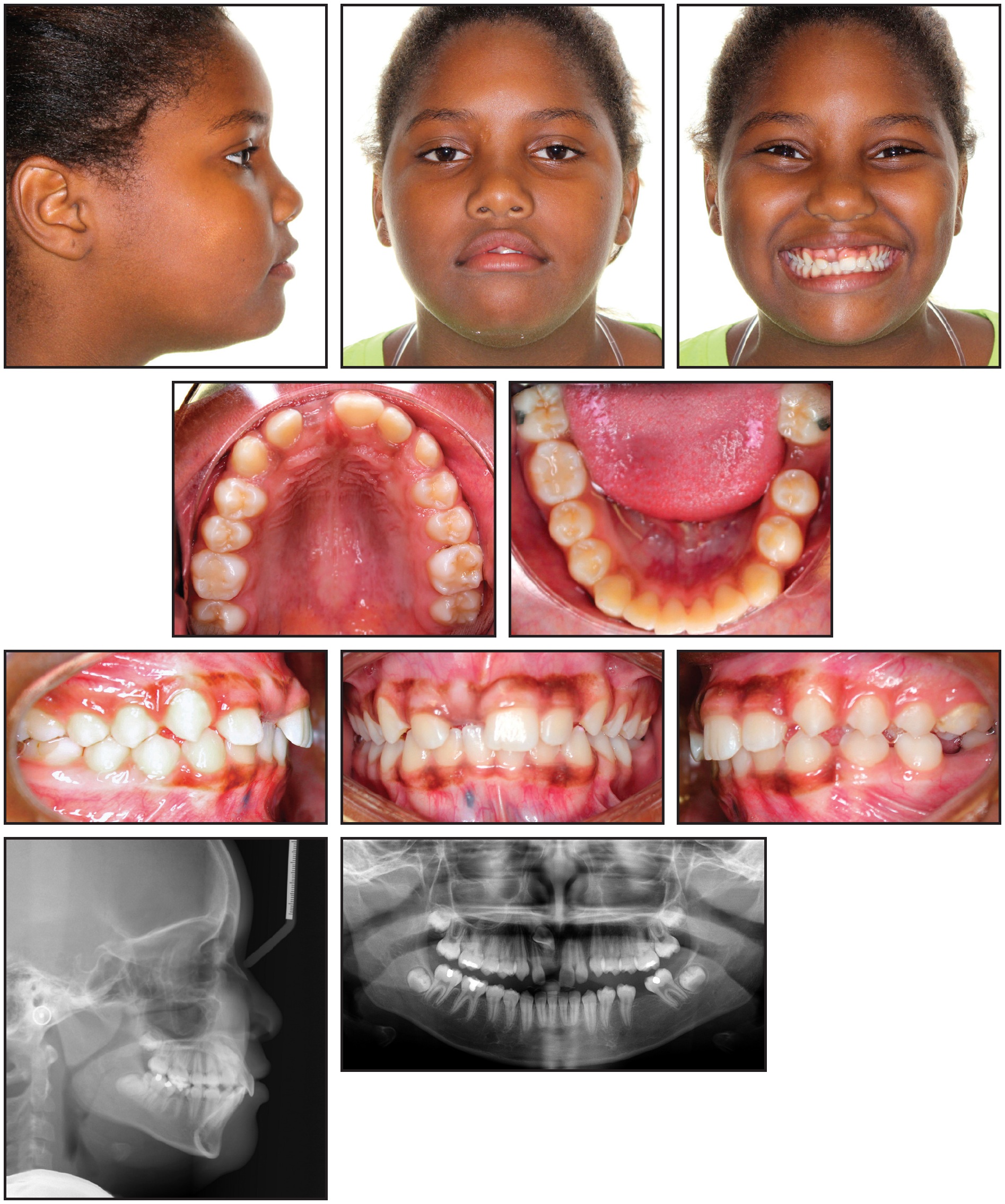
Fig. 4 11-year-old female patient with missing upper right central incisor and lower left first molar before treatment.
To address her chief complaint, two treatment options were discussed with the patient and her parents. Both started with surgical exposure of the upper right central incisor for extrusion into the arch, along with uprighting of the mesially tipped lower left second molar. In the first option, this would be followed by protraction using mini-implant anchorage and fixed-functional appliances for Class II molar correction on the left side. In the second option, the edentulous space would be maintained for an endosseous implant-based restoration, and fixed-functional appliances would be used for Class II correction on the left side. The parents chose the first option because it addressed the patient's concerns without the need for a dental implant.
After .022" MBT* brackets were bonded in both arches, .016" nickel titanium archwires were placed for alignment. A sequence of .016" x .022" and .019" x .025" nickel titanium wires was followed, after about five months, by .019" x .025" stainless steel. At that point, the patient was referred for closed surgical exposure of the upper right central incisor. One month after exposure of the tooth, 50-75g of force was applied with an elastomeric thread to guide its eruption. After initial leveling and alignment in the mandibular arch, excluding the lower left second molar, an .019" x .025" beta titanium cantilever spring was inserted in the lower left second-molar tube and hooked between the canine and premolar (Fig. 5).
Fig. 5 After six months of treatment, with .019" × .025" stainless steel archwires in place, cantilever spring inserted in lower left second-molar tube and hooked between canine and premolar to upright mesially tipped second molar. Exposed upper right central incisor guided into arch using elastomeric thread.
The anchorage unit consisted of the entire mandibular archwire except for the left second molar. The intrusive cantilever spring was designed to exert 50g of intrusive force anteriorly and a distal tipback moment of 1,000-1,250g-mm on the mesially tipped molar (Fig. 6). After the lower left second molar had been uprighted for six months, 7-8mm of edentulous space could be seen between it and the second premolar (Fig. 7).
To further level and align the uprighted second molar with the rest of the lower arch, a continuous .016" x .022" nickel titanium archwire was placed. Three months later, an .019" x .025" stainless steel archwire was placed and a 1.8mm x 8mm mini-implant** was inserted interdentally between the lower left premolars. The lower left second-premolar bracket was removed, and bands were placed. A lower alginate impression was sent to the laboratory for fabrication of the previously described molar protraction appliance (Fig. 8).
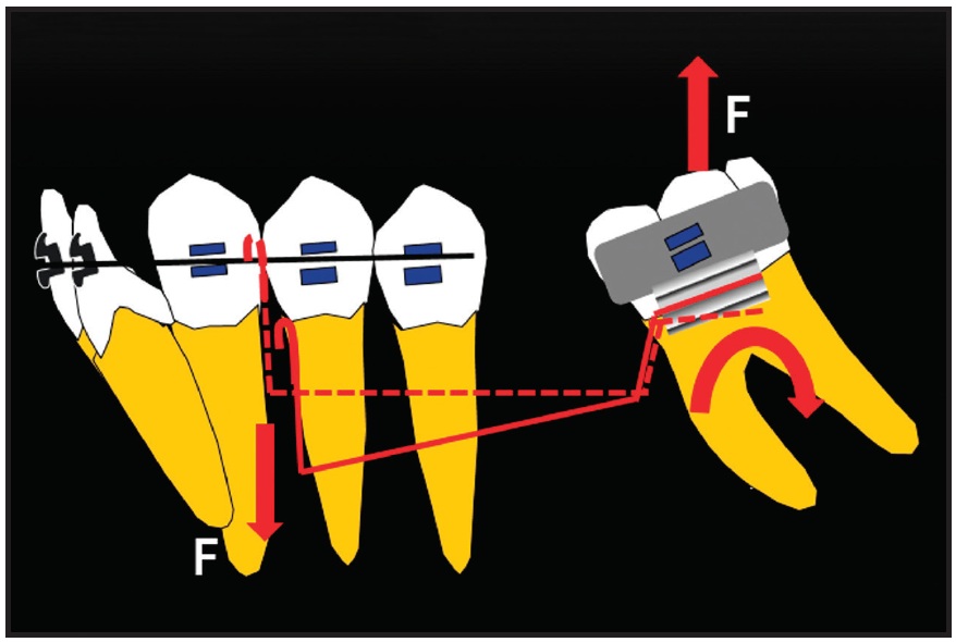
Fig. 6 Force system of cantilever spring for uprighting lower second molar.
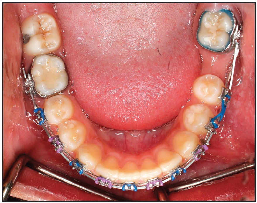
Fig. 7 Edentulous lower left first-molar space after six months of uprighting second molar.
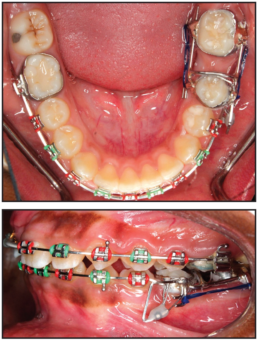
Fig. 8 After 16 months of treatment, lower molar-protraction appliance cemented in place; stainless steel power arm splinted to mini-implant between lower left premolars and cinched in buccal premolar tube for indirect anchorage.
Every six weeks, the appliance was reactivated by attaching new elastomeric chain on both the buccal and lingual sides. The lower left second molar was mesialized in nine months, with only .5mm of anchorage loss of the second premolar (Fig. 9). The appliance was then removed, and a panoramic x-ray indicated that the movement was close to translation. At this point, the buccal segments were in an end-on Class II relationship. A fixed-functional appliance (Forsus Fatigue Resistant Device*) was then delivered to be worn for six months. After the anteroposterior discrepancy was corrected, finishing was carried out with .016" x .022" beta titanium archwires and light seating elastics.
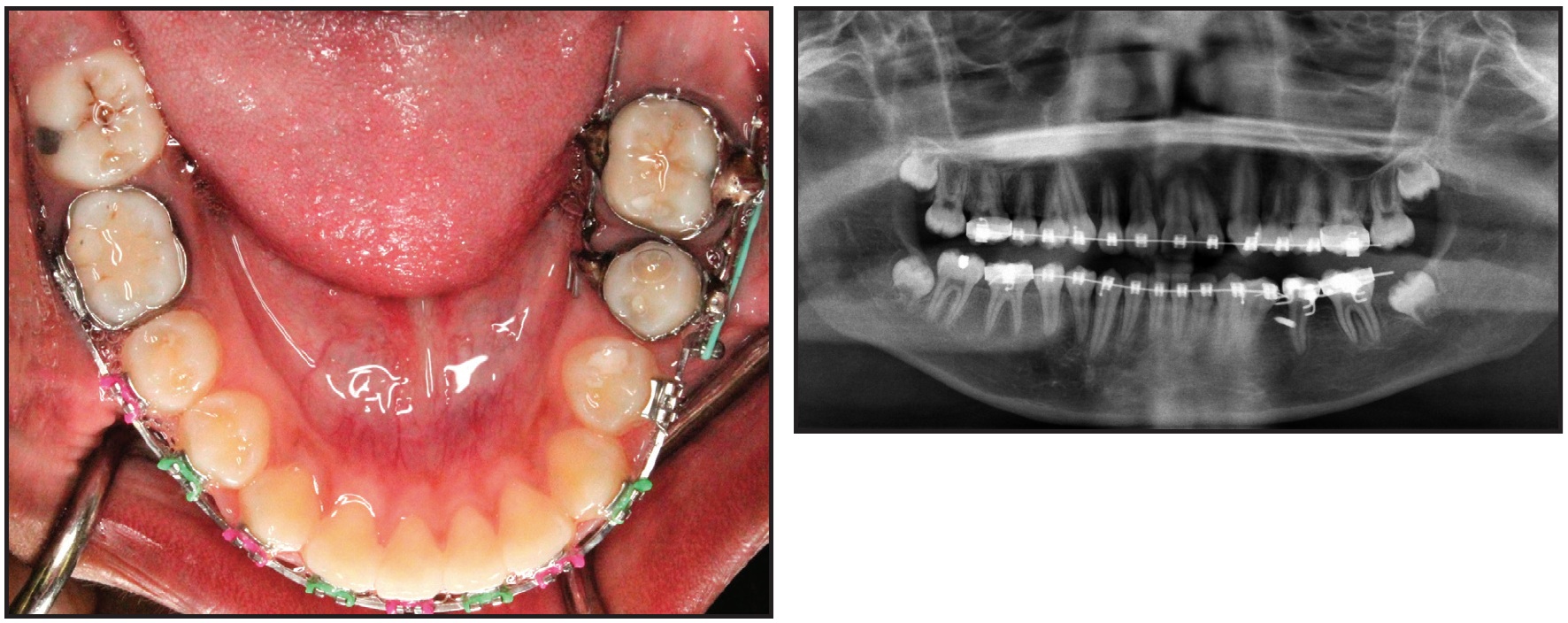
Fig. 9 Lower left second molar mesialized in nine months, with minimal loss of anchorage.
After 37 months of treatment, the orthodontic appliances were removed. A Hawley retainer was fabricated for the maxillary arch, and a 3-3 fixed lingual retainer was bonded in the mandibular arch.
The patient and parents were highly satisfied with the treatment outcome. The impacted upper right central incisor was brought into the arch, the lower left second molar was mesialized to close the missing first-molar space, and the end-on Class II buccal segments on the left side were corrected (Fig. 10A). Cephalometric analysis showed a slight increase in SNB and no change in the vertical dimension (Table 1). The panoramic radiograph and cephalometric superimpositions confirmed an upright lower left second molar in the first-molar space, with the third molar substituting for the second molar (Fig. 10B).
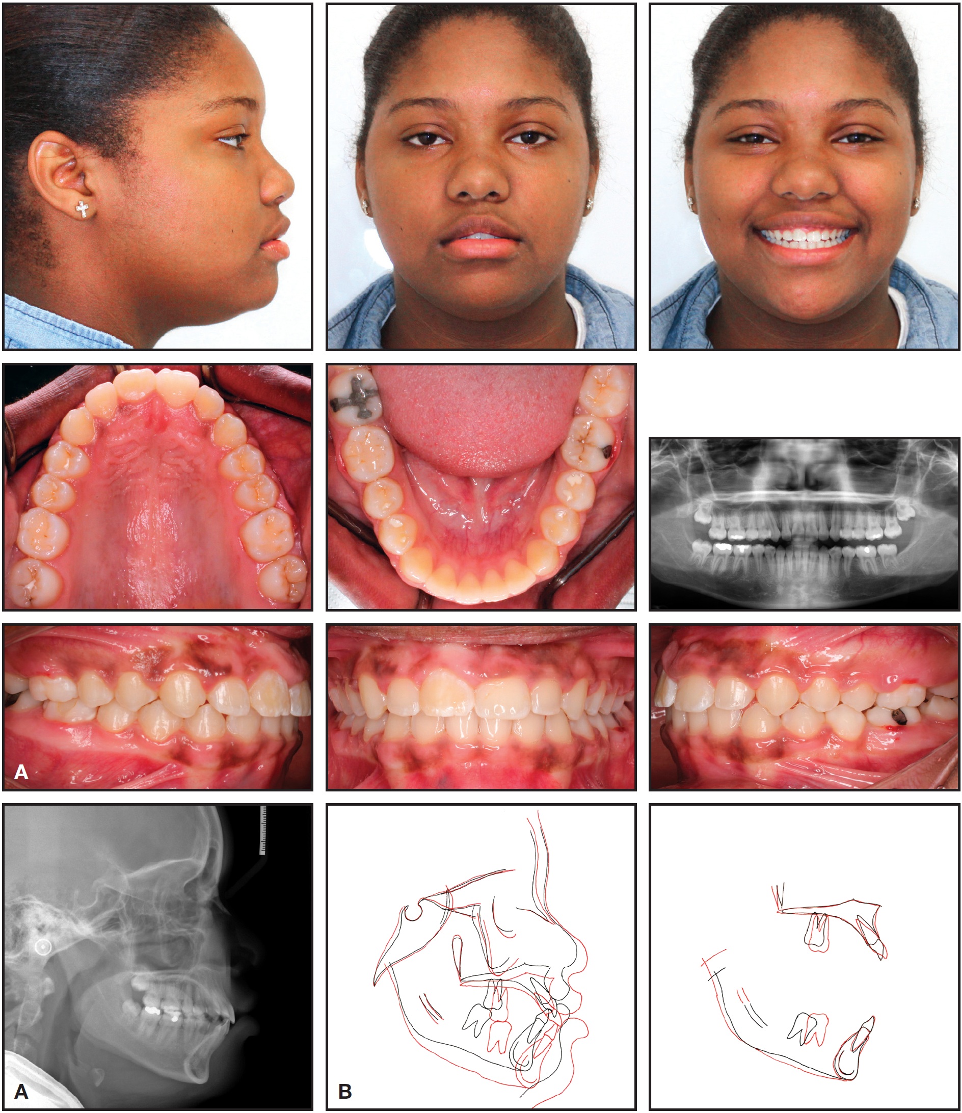
Fig. 10 A. Patient after 37 months of treatment. B. Superimposition of pre- and post-treatment cephalometric tracings.
Discussion
Lower-molar protraction is challenging. Although biomechanical concepts provide a good indication of the factors affecting molar protraction, other variables such as masticatory forces, individual variation in the rate of tooth movement, and permanent deformation of archwires add complexity to the force system, making prediction of results imprecise.9 Understanding these concepts can help avoid potential side effects and improve treatment efficiency.
In patients with missing lower first molars, protraction can be reliably achieved using the appliance described in this article, combined with indirect anchorage from mini-implants. Based on our experience, this appliance has been more efficient in younger adolescents than in adult patients. Further research is needed to establish its true effectiveness.
ACKNOWLEDGMENT: We thank Dr. Saleh Alwadei for finishing this patient.
FOOTNOTES
- *Trademark of 3M Unitek, Monrovia, CA; www.3MUnitek.com.
- **Unitek Temporary Anchorage Device System, 3M Unitek, Monrovia, CA; www.3MUnitek.com.
REFERENCES
- 1. Roberts, W.E.; Helm, F.R.; Marshall, K.J.; and Gongloff, R.K.: Rigid endosseous implants for orthodontic and orthopedic anchorage, Angle Orthod. 59:247-256, 1989.
- 2. Hom, B.M. and Turley, P.K.: The effects of space closure of the mandibular first molar area in adults, Am. J. Orthod. 85:549-469, 1984.
- 3. Markic, G.; Katsaros, C.; Pandis, N.; and Eliades, T.: Temporary anchorage device usage: A survey among Swiss orthodontists, Prog. Orthod. 15:29, 2014.
- 4. Cousley, R.: Molar protraction, in The Orthodontic Mini-implant Clinical Handbook, Wiley Blackwell, West Sussex, United Kingdom, 2013, pp. 83-98.
- 5. Nihara, J.; Gielo-Perczak, K.; Cardinal, L.; Saito, I.; Nanda, R.; and Uribe, F.: Finite element analysis of mandibular molar protraction mechanics using miniscrews, Eur. J. Orthod. 37:95-100, 2015.
- 6. Kojima, Y.; Fukui, H.; and Miyajima, K.: The effects of friction and flexural rigidity of the archwire on canine movement in sliding mechanics: A numerical simulation with a 3-dimensional finite element method, Am. J. Orthod. 130:275e1- 275e10, 2006.
- 7. Kojima, Y. and Fukui, H.: Numerical simulation of canine retraction by sliding mechanics, Am. J. Orthod. 127:542-551, 2005.
- 8. Kojima, Y. and Fukui, H.: Numerical simulations of canine retraction with T-loop springs based on the updated momentto- force ratio, Eur. J. Orthod. 34:10-18, 2012.
- 9. Burstone, C.J.: Self-ligation and friction: Fact and fantasy, in Effective and Efficient Orthodontic Tooth Movement, Monograph 48, Craniofacial Growth Series, ed. S.D. Kapila, N. Hatch, and J.A. McNamara Jr., Department of Orthodontics and Pediatric Dentistry and Center for Human Growth, University of Michigan, Ann Arbor, MI, 2011, pp. 1-25.
- 10. Janakiraman, N.; Uribe, F.; and Nanda, R.: Incorporating TADS and sound mechanics for efficient orthodontic treatment, in Expedited Orthodontics: Improving the Efficiency of Orthodontic Treatment Through Novel Technologies, Monograph 51, Craniofacial Growth Series, ed. S.D. Kapila, J. Nervina, and N. Hatch, Department of Orthodontics and Pediatric Dentistry and Center for Human Growth, University of Michigan, Ann Arbor, MI, 2015, pp. 1-26.
- 11. Upadhyay, M.; Yadav, S.; and Nanda, R.: Biomechanical basis of extraction space closure, in Esthetics and Biomechanics in Orthodontics, Saunders, Philadelphia, 2012, p. 108.
-
 DR. JANAKIRAMAN
 -
 DR. ALRUSHAID
 -
 DR. UPADHYAY
 -
 DR. NANDA
 -
 DR. URIBE