OVERVIEW
Anatomical Guidelines for Miniscrew Insertion: Palatal Sites
(Editor's Note: In this quarterly column, JCO provides an overview of a clinical topic of interest to orthodontists. Contributions and suggestions for future subjects are welcome.)
A previous Overview described suitable sites for vestibular miniscrew insertion.1 Although these locations are commonly used in orthodontic applications because of their ease of access, the interradicular spaces are limited by the proximity of neighboring roots (Fig. 1), presenting the following problems:
- Risk of damaging the roots or the periodontium.
- Possibility of miniscrew-root contact resulting in early screw failure.
- Risk of screw fracture during placement, due to the narrower miniscrew dimensions needed for interradicular positions.
- A loss rate as high as 25%.2
These risk factors can be avoided by using "rootless areas" such as the hard palate, the maxillary tuberosity, or the portions of the zygomatic arches adjacent to the maxilla. The tuberosity cannot be regarded as entirely safe, since unerupted third molars or thick layers of gingiva may prevent successful insertion3 (Fig. 2).
Similar articles from the archive:
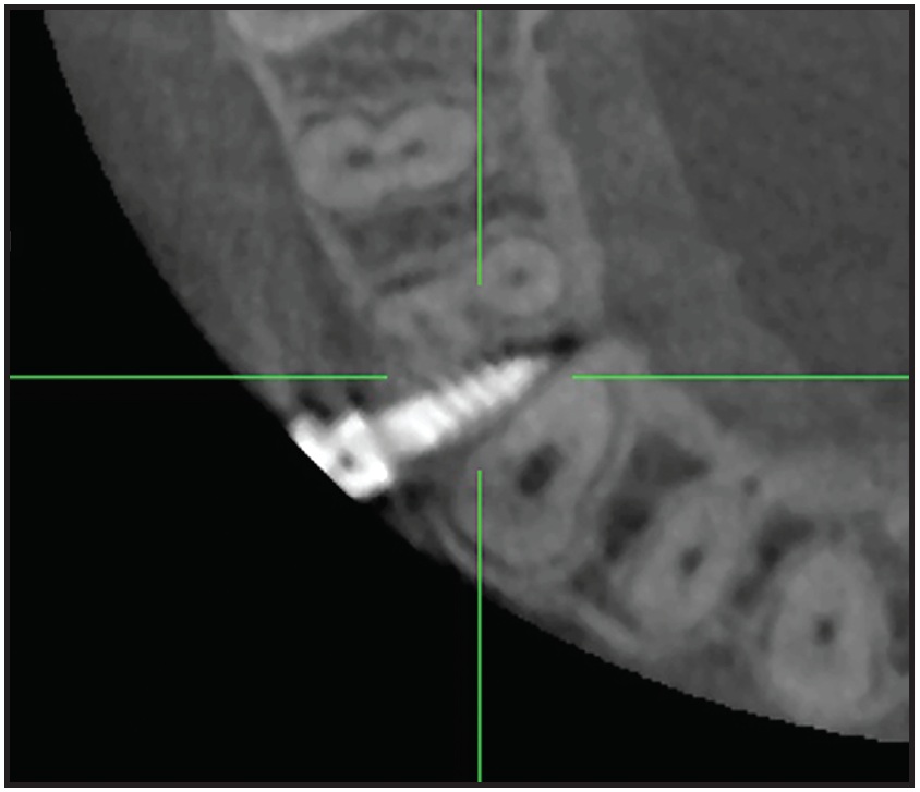
Fig. 1 Insufficient interradicular space for miniscrew insertion in buccal alveolar process, potentially leading to miniscrew failure or lesions on root surface.
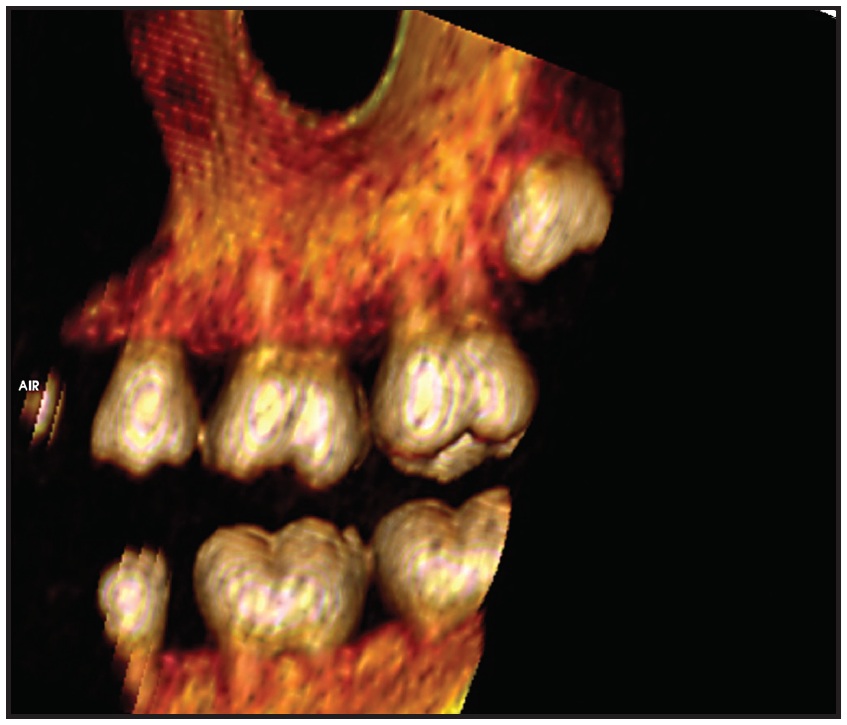
Fig. 2 Thick gingival tissue and unerupted molars can impede miniscrew insertion in maxillary retromolar area.
Insertion into the inferior portion of the zygomatic arch carries the risk of perforating the maxillary sinus.4 Therefore, the only safe alternatives to buccal miniscrew placement are in the palate.
In the mandible, where lingual screw insertion is associated with higher loss rates,5 the mentalis region is better suited for miniscrews and miniplates.6In the maxilla, the hard palate appears to be an ideal insertion site. While the anterior palate definitely offers sufficient bone, consensus has yet to be reached regarding the minimal amount of bone required to avoid penetration into neighboring anatomical structures. Liou and colleagues suggested 2mm,7 Poggio and colleagues recommended 1mm,3 and Maino and colleagues considered .5mm to be sufficient.8
Miniscrew dimensions must be selected according to the desired insertion site, considering that smaller screw diameters present a higher risk of fracture during placement. Although insertion into attached gingiva is preferable, the thickness of the tissue must not be excessive; at least half the screw length should be embedded in cortical bone, with the head of the screw still accessible. The shaft of the screw must not impede root movement, and the location should allow biomechanical alterations to be made in the treatment plan if necessary. The anterior palate satisfies all these requirements.
In 1996, Wehrbein and colleagues described a highly sophisticated implant system for the anterior palate9; three years later, this group reported a 100% success rate for en masse retraction of upper anterior teeth, a biomechanically demanding procedure.10 Park has documented a 100% success rate for miniscrews inserted in the anterior palate.11 Wilmes and colleagues, using coupled miniscrews and a rigid miniplate in the anterior palate, demonstrated high stability and success rates.12 The anterior palate may also offer greater patient comfort and, thus, greater acceptance compared to other locations.13
Palatal Hard Tissue
The main factor determining the success of miniscrew placement, whether in the buccal alveolus or the palate, is the quantity of surrounding bone. Since the introduction of the Orthosystem* palatal implant by Wehrbein and colleagues,9 the anterior hard palate has become the most thoroughly investigated region for skeletal anchorage in orthodontics, including three-dimensional computed-tomography (CT) studies.
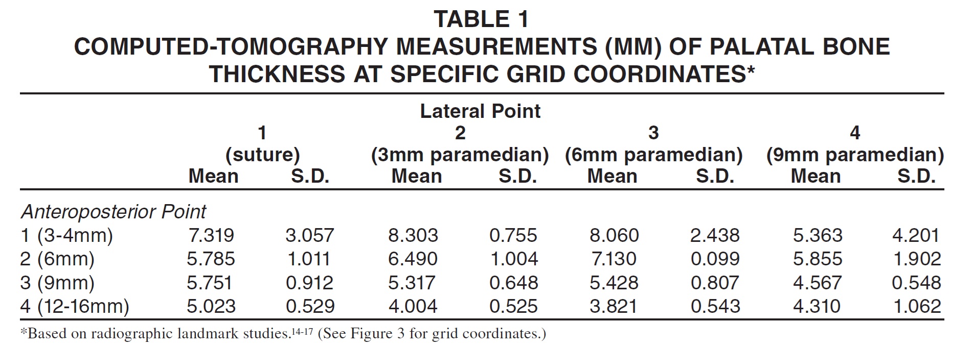
Two substantially different investigation protocols have been used to determine landmarks and coordinates in this region. In radiographic observation, measurements are made from the distal aspect of the incisive foramen.14-17 In the clinical anatomic method, the contact points between the canine, premolars, and molars are used as references, with lateral measurements made from the midpalatal suture.18 lowing studies are based on a palatal-vault measurement grid (Fig. 3). The first coordinate is the anteroposterior distance from the distal margin of the incisive foramen (3-4mm, 6mm, 8-9mm, or 12-16mm). The second coordinate is a lateral measurement from the midpalatal suture (3mm, 6mm, or 9mm). A coordinate of 1/3, for example, indicates a point 3-4mm posterior to the incisive foramen and 6mm lateral to the suture.
Radiographic Landmarks
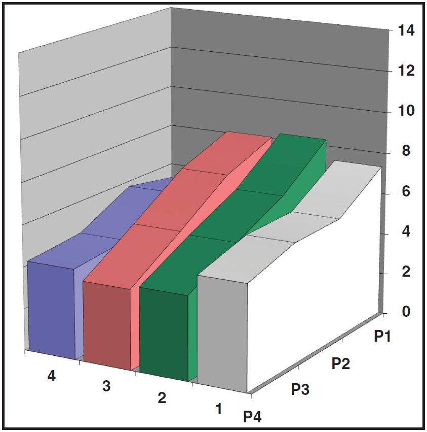
The reviewed radiographic landmark studies clearly demonstrate that the thickest vertical bone repositories are located 3-4mm distal to the incisive foramen and 3mm paramedian to the palatal suture (Fig. 4, Table 1).14-17
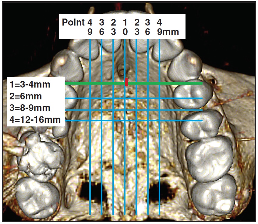
Fig. 3 Palatal-vault grid used in analysis of radiographic and clinical landmarks (green line indicates anterior limit for favorable palatal miniscrew insertion; red square shows distance from incisive foramen to reference line).
Both Crismani and colleagues19 and Cousley20 have published guidelines for safe insertion in the anterior hard palate, describing limitations and risks. The screw should be inserted perpendicular to the palatal surface and angled toward the incisor roots to ensure optimal retention and effectiveness (Fig. 5A). Although an occlusal view suggests the possibility of root contact, 3D CT scans prove that such concerns are unfounded (Fig. 5B).
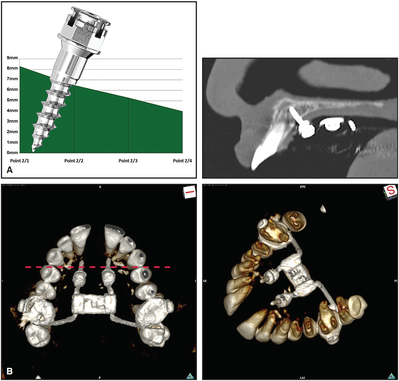
Fig. 5 A. Insertion of palatal miniscrew perpendicular to palatal bone surface at point 2/2. B. Rotated three-dimensional reconstruction shows no contact with incisor roots, despite angulation of screw.
While the midpalatal suture might appear to be the best insertion site, considering its high bone quantity and quality, this conclusion is not borne out by the literature. The median suture (coordinate 1/1, 3-4mm posterior to the incisive foramen) does have a thick vertical layer of bone, but there is a substantial standard deviation in this thickness. Bernhart and colleagues found a mean bone thickness of only 2.94mm at the suture and, therefore, recommended an insertion site 3-6mm paramedian to the suture and 6-9mm distal to the incisive foramen,15 emphasizing the interindividual variability of the 22 patients (age 13-48) in their study.
In comparison, Gracco and colleagues reported 9.04mm ± 2.44mm of bone at coordinate 1/1 in a group of 52 patients (age 10-15).21 Kang and colleagues found smaller mean values of 5.6mm ± 1.6mm in a group of 18 patients (age 18-35); they also showed a bone thickness of 9.2mm ± 2.5mm just 3mm lateral to the suture.16 Based on the high standard deviations, these authors recommended a more individualized diagnostic regimen, with more anterior screw placement closer to the suture. King and colleagues evaluated 138 patients (age 10-19), but did not measure bone thickness at the midpalatal suture.17 They advised placing screws 4mm distal to the incisive foramen and 3mm lateral to the suture.
Wehrbein reported considerable success with implants in the anterior palate, both medial and paramedian to the suture.22 On the other hand, Kim and colleagues recorded a success rate of 88.2% for miniscrews placed in the palatal suture.23 This difference could be attributable to the narrower diameter of the miniscrews, but some CT scans have also shown reduced bone height and/or minimal levels in interdigitation of the suture (Fig. 6A)--factors that could significantly influence the results from a small sample such as that in the Kim study. Wilmes and Drescher have developed a system that combines the ease of use of miniscrews with the stability of palatal implants, reporting higher success rates for both medial and paramedian locations (Figs. 6B,C).24

Fig. 6 A. Computed-tomography (CT) scan, sliced 3-4mm posterior to incisive foramen, demonstrating minimal visibility of interdigitation in suture (blue and green rectangles represent typical dimensions of palatal implant and miniscrew, respectively). B. Frog appliance (left) with skeletal anchorage used for molar distalization with paramedian miniscrews (OrthoEasy,** 1.7mm). Beneslider*** (right) used for molar distalization with sutural miniscrews (Benefit,*** 2.3mm). C. Palatal portion of vomer or nasal septum requires medial insertion to ensure adequate bone.
Clinical Anatomic Landmarks
Although the radiographic method is more reliable than clinical observation because it is unaffected by tooth movement, the disadvantage of radiographic measurement is the difficulty of interpreting and applying the results in clinical practice. Baumgaertel proposed easily identifiable clinical landmarks on dental crowns in his CT study, with lateral measurements following the suture at distances of 2mm, 4mm, 6mm, 8mm, and 10mm.18 The areas 2mm paramedian to the suture and between the canine and first-premolar contact points (8.7mm ± 2.3mm of bone) and first- and second-premolar contact points (8.68mm ± 3.68mm) were described as ideal insertion locations. While Baumgaertel's results concur with those of the radiographic landmark studies, this clinical method should be applied only to dental arches with minimal tooth movement.
Using the measurement grid shown in Figure 3, we determined the anteroposterior distance between the distal margin of the incisive foramen and a virtual line connecting the contact points between the upper canine and first premolar on either side of the arch in 72 permanent-dentition patients without upper-arch crowding. The median distance was 1.4mm, but values ranged from 0 to 4.4mm, with a standard deviation of 1.2mm, indicating substantial individual variability. In some cases, the contacts between the upper canines and first premolars may be on the same level as the distal margin of the incisive foramen.
Palatal Soft Tissue, Blood Vessels, and Nerves
The quality of the palatal gingiva, much like the quality and quantity of bone, is an important factor in determining the success of miniscrew anchorage. The thinner attached gingiva is most desirable for screw placement.25 While the mucosa is rather thick around the lateral aspects of the palatal arch, it forms a constant layer of only 1-4mm at the midpalatal suture distal to the incisive foramen26(Fig. 7)
Because blood-vessel density is low in the anterior palate (Fig. 8), the risk of iatrogenic injury from miniscrew insertion is minimal. The major palatine foramen with its dense vascular bundle can be problematic, however, if miniscrews are inserted in that area.
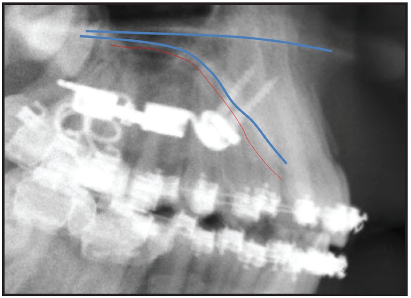
Fig. 7 Attached gingiva is only moderately thick at anterior palatal suture; note screw threads completely embedded in bone after penetration of mucosa.
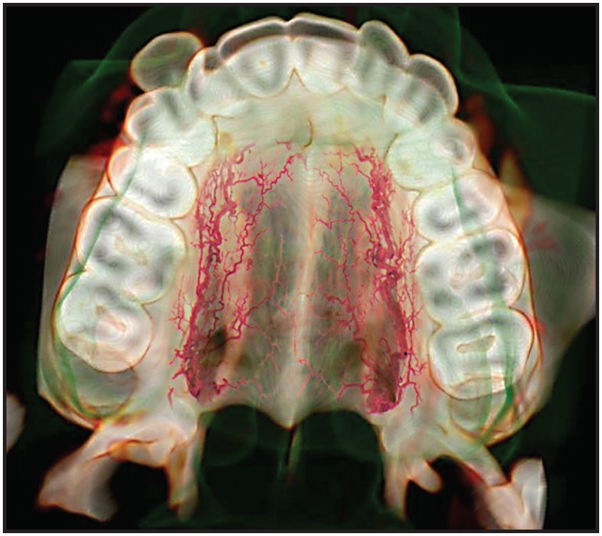
Fig. 8 Anterior palate has lower blood-vessel density than in posterior region.
Alternative Locations
The posterior palate has also been described as a suitable location for miniscrew applications such as skeletal support of posterior intrusion.27 Another alternative is the palatal alveolus between the maxillary first molar and second premolar, where the favorable position of the first molar's palatal root and the buccal angulation of the second premolar provide excellent access for direct insertion of a miniscrew (Fig. 9).
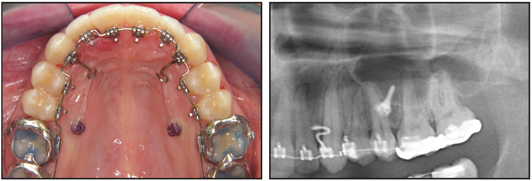
Fig. 9 Miniscrews inserted into palatal alveolus between roots of maxillary second premolars and first molars, another area with optimal cortical-plate thickness.
This location offers the largest interradicular space, a sufficiently wide cortical plate, and moderately thick attached gingiva.17 In a CT study of 21 subjects, we found results similar those of Poggio and colleagues3: an interradicular bone width of 5mm located 4-6mm apical to the alveolar crestal margin (Fig. 10).
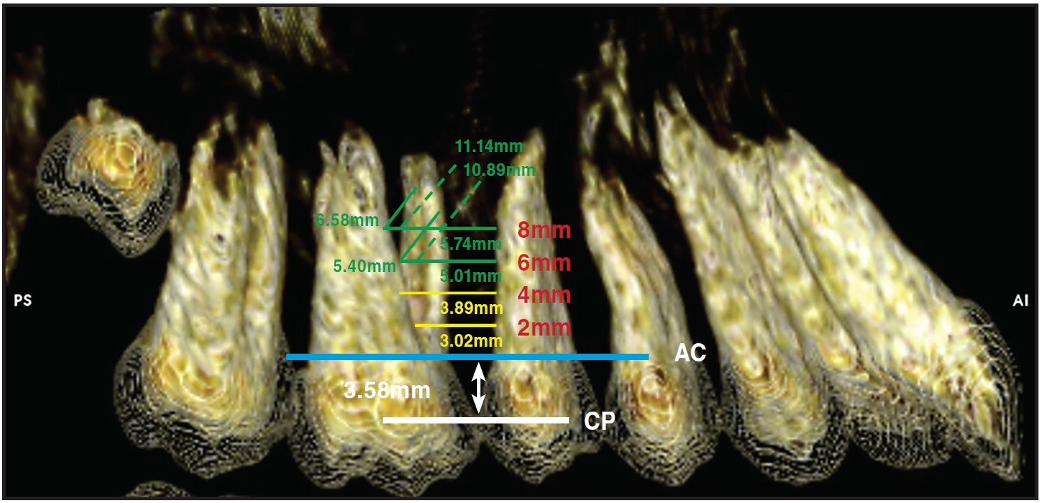
Fig. 10 CT evaluation of interradicular bone between maxillary first molars and second premolars in 21 patients, 2mm, 4mm, 6mm, and 8mm apical to alveolar crestal margin (CP = contact point; AC = alveolar crest).
Measuring from the interproximal contact point of the first molar and second premolar, we found optimal bone thickness 8-9mm apically. Miniscrews placed in this area can be useful in supporting posterior intrusion, en masse protraction, space closure, retraction, and molar distalization. Risk factors include occasionally thick mucosa and numerous blood vessels and nerves.28-32
Considering all the aforementioned parameters, the suitability of various miniscrew insertion locations in the hard palate can be evaluated and charted (Fig. 11). This information should enhance the clinician's ability to select appropriate locations for miniscrew placement.
Conclusion
The anterior palate appears to be one of the best sites for orthodontic miniscrews or palatal implants. Cortical bone is typically thicker in the palate than at buccal interradicular insertion sites, and favorable attached gingiva is readily available, ensuring high success rates. In addition, miniscrews placed in this area will not contact dental roots or inhibit tooth movement.
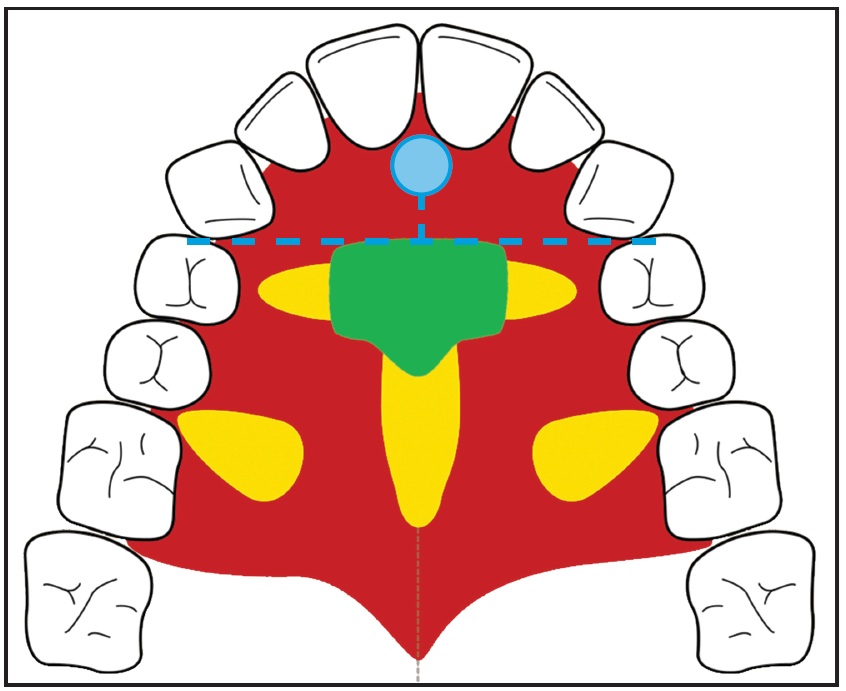
Fig. 11 Suitability of potential miniscrew insertion sites in palate (green = optimal; yellow = restricted due to individual variability in bone thickness; red = unsuitable because of thick mucosa or vascular bundles; blue dot = incisive foramen).
Skeletal anchorage in the anterior palate is optimal for supporting various treatment mechanics, including distalization, protraction of buccal teeth, rapid maxillary expansion, space closure, and intrusion mechanics (Fig. 12).
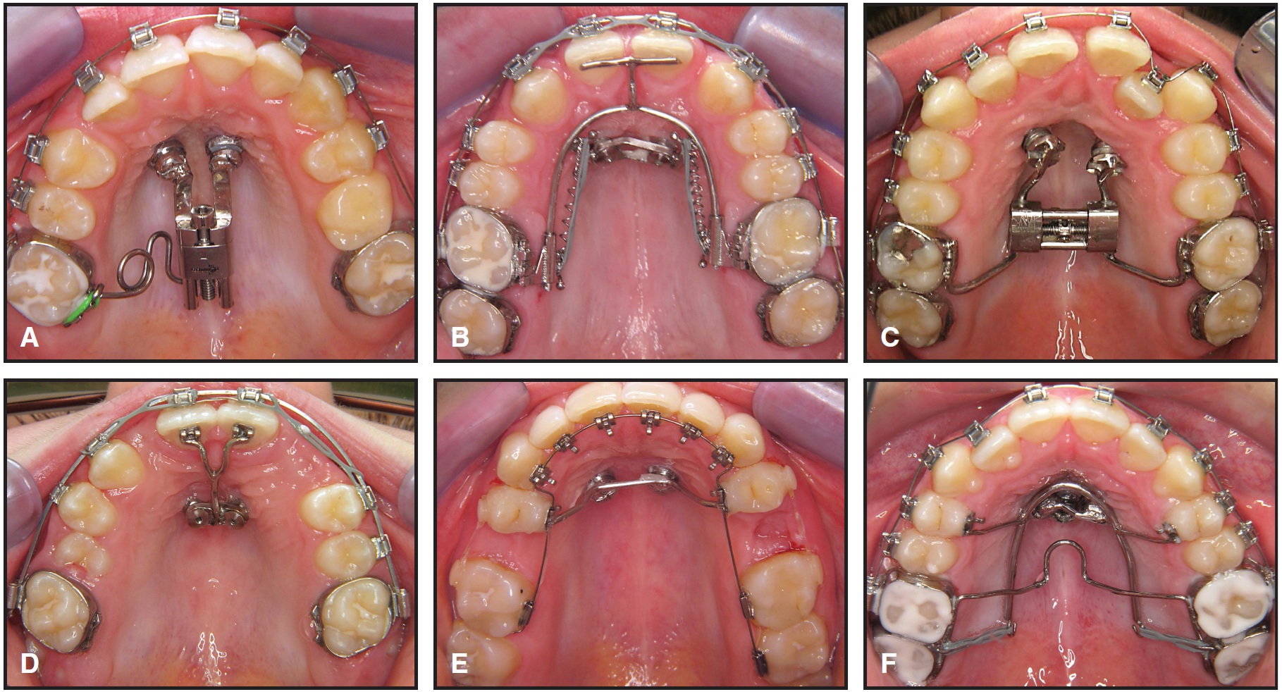
Fig. 12 Examples of uninhibited tooth movement available with skeletal anchorage in anterior palate. A. Unilateral molar distalization for anterior space creation, using K-Pendulum. B. Mesialization of buccal segments for space closure in case of congenitally missing lateral incisors, using mesial sliding appliance. C. Rapid maxillary expansion, using Hybrid RME. D. Space consolidation in canine substitution for congenitally missing lateral incisors, using T-arch. E. Molar protraction into spaces left by congenitally missing second premolars, using transpalatal bar. F. Posterior intrusion to assist in closing anterior open bite, using cantilever arch.
Biomechanics can be designed in nearly any direction and can usually be changed in midtreatment using the same anchorage setup. The palatal alveolus between the roots of the second premolar and first molar may be considered as an alternative miniscrew location, with some limitations.33
FOOTNOTES
- *Registered trademark of Straumann AG, Basel, Switzerland; www.straumann.com.
- **Registered trademark of Forestadent, Pforzheim, Germany; www.forestadent.com.
- ***Mondeal-PSM North America, Indio, CA; www.mondeal-ortho.com.
REFERENCES
- 1. Ludwig, B.; Glasl, B.; Kinzinger, G.S.M.; Lietz, T.; and Lisson, J.A.: Anatomical guidelines for miniscrew insertion: Vestibular interradicular sites, J. Clin. Orthod. 45:165-173, 2011.
- 2. Chen, Y.J.; Chang, H.H.; Lin, H.Y.; Lai, E.H.; Hung H.C.; and Yao, C.C.: Stability of miniplates and miniscrews used for orthodontic anchorage: Experience with 492 temporary anchorage devices, Clin. Oral Impl. Res. 19:1188-1196, 2008.
- 3. Poggio, P.M.; Incorvati, C.; Velo, S.; and Carano, A.: "Safe zones" A guide for miniscrew positioning in the maxillary and mandibular arch, Angle Orthod. 76:191-197, 2006.
- 4. Gracco, A.; Tracey, S.; and Baciliero, U.: Miniscrew insertion and the maxillary sinus: An endoscopic evaluation, J. Clin. Orthod. 44:439-443, 2010.
- 5. Wiechmann, D.; Meyer, U.; and Buchter, A.: Success rate of mini- and micro-implants used for orthodontic anchorage: A prospective clinical study, Clin. Oral Impl. Res. 18:263-267, 2007.
- 6. Heymann, G.C.; Cevidanes, L.; Cornelis, M.; De Clerck, H.J.; and Tulloch, J.F.: Three-dimensional analysis of maxillary protraction with intermaxillary elastics to miniplates, Am. J. Orthod. 137:274-284, 2010.
- 7. Liou, E.J.; Pai, B.C.; and Lin, J.C.: Do miniscrews remain stationary under orthodontic forces? Am. J. Orthod. 126:42- 47, 2004.
- 8. Maino, B.G.; Mura, P.; and Bednar, J.: Miniscrew implants: The Spider Screw anchorage system, Semin. Orthod. 11:40-46, 2005.
- 9. Wehrbein, H.; Glatzmaier, J.; Mundwiller, U.; and Diedrich, P.: The Orthosystem--a new implant system for orthodontic anchorage in the palate, J. Orofac. Orthop. 57:142-153, 1996.
- 10. Wehrbein, H.; Feifel, H.; and Diedrich, P.: Palatal implant anchorage reinforcement of posterior teeth: A prospective study, Am. J. Orthod. 116:678-686, 1999.
- 11. Park, H.S.: Clinical study on success rate of microscrew implants for orthodontic anchorage, Kor. J. Orthod. 33:151-156, 2003.
- 12. Wilmes, B.; Drescher, D.; and Nienkemper, M.: A miniplate system for improved stability of skeletal anchorage, J. Clin. Orthod. 43:494-501, 2009.
- 13. Gunduz, E.; Schneider-Del Savio, T.T.; Kucher, G.; Schneider, B.; and Bantleon, H.P.: Acceptance rate of palatal implants: A questionnaire study, Am. J. Orthod. 126:623-626, 2004.
- 14. Gracco, A.; Lombardo, L.; Cozzani, M.; and Siciliani, G.: Quantitative evaluation with CBCT of palatal bone thickness in growing patients, Prog. Orthod. 7:164-174, 2006.
- 15. Bernhart, T.; Vollgruber, A.; Gahleitner, A.; Dortbudak, O.; and Haas, R.: Alternative to the median region of the palate for placement of an orthodontic implant, Clin. Oral Impl. Res. 11:595-601, 2000.
- 16. Kang, S.; Lee, S.J.; Ahn, S.J.; Heo, M.S.; and Kim, T.W.: Bone thickness of the palate for orthodontic mini-implant anchorage in adults, Am. J. Orthod. 131:S74-S81, 2007.
- 17. King, K.S.; Lam, E.W.; Faulkner, M.G.; Heo, G.; and Major, P.W.: Vertical bone volume in the paramedian palate of adolescents: A computed tomography study, Am. J. Orthod. 132:783-788, 2007.
- 18. Baumgaertel, S.: Quantitative investigation of palatal bone depth and cortical bone thickness for mini-implant placement in adults, Am. J. Orthod. 136:104-108, 2009.
- 19. Crismani, A.G.; Bernhart, T.; Tangl, S.; Bantleon, H.P.; and Watzek, G.: Nasal cavity perforation by palatal implants: False-positive records on the lateral cephalogram, Int. J. Oral Maxillofac. Impl. 20:267-273, 2005.
- 20. Cousley, R.: Critical aspects in the use of orthodontic palatal implants, Am. J. Orthod. 127:723-729, 2005.
- 21. Gracco, A.; Lombardo, L.; Cozzani, M.; and Siciliani, G.: Quantitative evaluation of palatal bone thickness with cone beam computed tomography, European Orthodontic Society Congress, Berlin, Germany, June 2007.
- 22. Wehrbein, H.: Bone quality in the midpalate for temporary anchorage devices, Clin. Oral Impl. Res. 20:45-49, 2009.
- 23. Kim, Y.H.; Yang, S.M.; Kim, S.; Lee, J.Y.; Kim, K.E.; Gianelly, A.A.; and Kyung S.H.: Midpalatal miniscrews for orthodontic anchorage: Factors affecting clinical success, Am. J. Orthod. 137:66-72, 2010.
- 24. Wilmes, B. and Drescher, D.: A miniscrew system with interchangeable abutments, J. Clin. Orthod. 42:574-580, 2008.
- 25. Costa, A.: Intraoral hard and soft tissue dimensions for temporary anchorage device placement, in OrthoTADs: The Clinical Guide and Atlas, 1st ed., ed. J.B. Cope, Under Dog Media LP, Dallas, 2007, pp. 109-117.
- 26. Kim, H.J.; Yun, H.S.; Park, H.D.; Kim, D.H.; and Park, Y.C.: Soft-tissue and cortical-bone thickness at orthodontic implant sites, Am. J. Orthod. 130:177-182, 2006.
- 27. Kravitz, N.D.; Kusnoto, B.; Tsay, P.T.; and Hohlt, W.F.: Intrusion of overerupted upper first molar using two orthodontic miniscrews: A case report, Angle Orthod. 77:915-922, 2007.
- 28. Kravitz, N.D. and Kusnoto, B.: Risks and complications of orthodontic miniscrews, Am. J. Orthod. 131:S43-51, 2007.
- 29. Ludwig, B.; Baumgaertel, S.; and Bowman, S.J.: Mini-Implants in Orthodontics: Innovative Anchorage Concepts, Quintessence Publishing Co. Ltd., London, 2008.
- 30. Cheng, N.; Zhang, K.; and Song, R.: [Applied anatomy of arterial supply for the soft palate], Zhonghua Zheng Xing Wai Ke Za Zhi 16:208-211, 2000.
- 31. Fernandes, A.; Wafae, N.; and Yamashita, H.K.: Angiographic study of the arterial supply to the palatine mucoperiosteum, Ann. Anat. 184:41-44, 2002.
- 32. Gauthier, A.; Lezy, J.P.; and Vacher, C.: Vascularization of the palate in maxillary osteotomies: Anatomical study, Surg. Radiol. Anat. 24:13-17, 2002.
- 33. Bowman, S.J.: Thinking outside the box with mini-screws, in Microimplants as Temporary Anchorage in Orthodontics, ed. J.A. McNamara Jr. and K.A. Ribbens, Craniofacial Growth Series, vol. 45, University of Michigan, Ann Arbor, MI, 2008, pp. 327-390.
-
 DR. LUDWIG
 -
 DR. GLASL
 -
DR. BOWMAN
-
DR. WILMES
-
DR. KINZINGER
-
DR. LISSON
Drs. Ludwig and Glasl are Instructors, Dr. Kinzinger is a Professor, and Dr. Lisson is Professor and Head, Department of Orthodontics, University of Homburg, Saar, Germany. Drs. Ludwig and Glasl are also in the private practice of orthodontics at Am Bahnhof 54, 56841 Traben-Trarbach, Germany. Dr. Wilmes is an Associate Professor, Department of Orthodontics, University of Düsseldorf, Düsseldorf, Germany. Dr. Bowman is an Adjunct Associate Professor, St. Louis University, St. Louis, MO; an Instructor, University of Michigan at Ann Arbor and Case Western Reserve University, Cleveland, OH; and in the private practice of orthodontics in Portage, MI. Drs. Ludwig and Bowman are Contributing Editors of the Journal of Clinical Orthodontics. E-mail Dr. Ludwig at bludwig@kieferorthopaedie-mosel.de.