The Dynamax System: A New Orthopedic Appliance
Skeletal Class II treatment requires harmonization of the structures supporting the dentition, as well as tooth movement, if an esthetic facial appearance is to be achieved for the patient. Harmonized skeletal bases need less tooth movement and, in particular, less incisor root movement to produce the dental correction. Therefore, two-phase treatment, beginning with a first stage of orthopedic therapy, is now a useful approach.
Although a number of appliances are available for orthopedic or functional therapy, many of these are relatively inefficient or have unfavorable dentoalveolar side effects. This article presents a new design that incorporates features of the original Bass Orthopedic System,1-6 but with a much simplified construction and clinical technique. It is more comfortable for the patient and hence is readily accepted for full-time wear.
Appliance Design
The Dynamax appliance* has two components: the upper part is removable, while the lower can be either removable (Fig. 1) or fixed as a lingual arch with bands cemented to the first molars. The fixed version is particularly helpful in the late mixed dentition, when mechanical retention of a removable appliance may be problematic. It also acts as a space maintainer to preserve the leeway space from the deciduous second molars and thus reduce the need for extractions.7 A fixed component requires less patient cooperation and permits lower brackets to be bonded simultaneously.
Similar articles from the archive:
Maxillary Component
The maxillary part (Fig. 2) features:
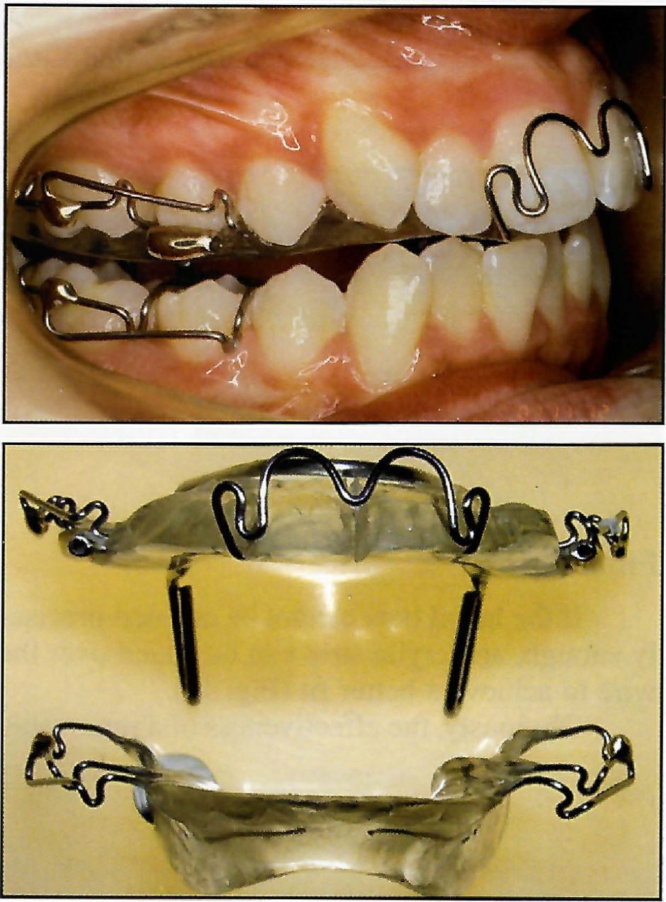
Fig. 1 Dynamax appliance with removable lower component.
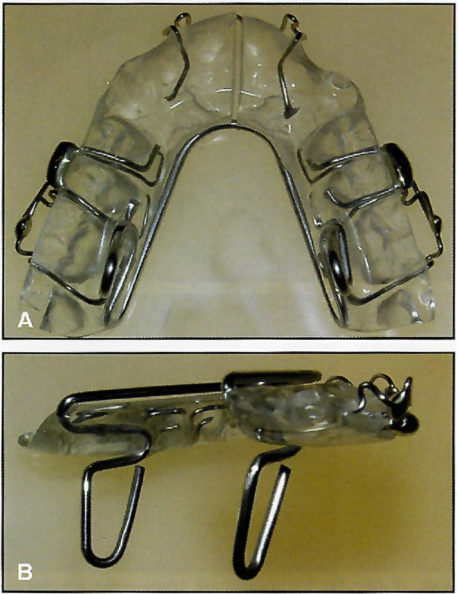
Fig. 2 A. Maxillary portion of appliance, with acrylic kept as thin as possible. B. Vertical springs.
1. Retention by means of Adams clasps on the first molars and a modified anterior torquing spring.2,6,8 Clasps on the deciduous second molars or second premolars are optional. Crozat-type clasps may be used to advantage in the mixed dentition, because they are generally more retentive than Adams clasps at this stage. Acrylic capping of the buccal segments and incisors maybe used for added retention, or instead of clasps to make a simplified version when retention is not a problem.
2. Maxillary expansion, produced by a palatal spring. This is generally required to avoid the development of posterior crossbite as the mandible grows forward. It also provides more space in the maxillary arch.
3. Mandibular advancement, produced by vertical spring projections in the first molar area that engage lingual "shoulders" on the mandibular component (Fig. 3). The contact prevents the mandible from dropping back from its protrusive position, which is generally 3-4mm forward of centric relation. Because the projections are on the lingual side of the teeth, there is no occlusal interference (Fig. 4). This avoids the undesirable increase in lower facial height that may accompany the use of orthopedic appliances such as the activator or Twin Block.4,9
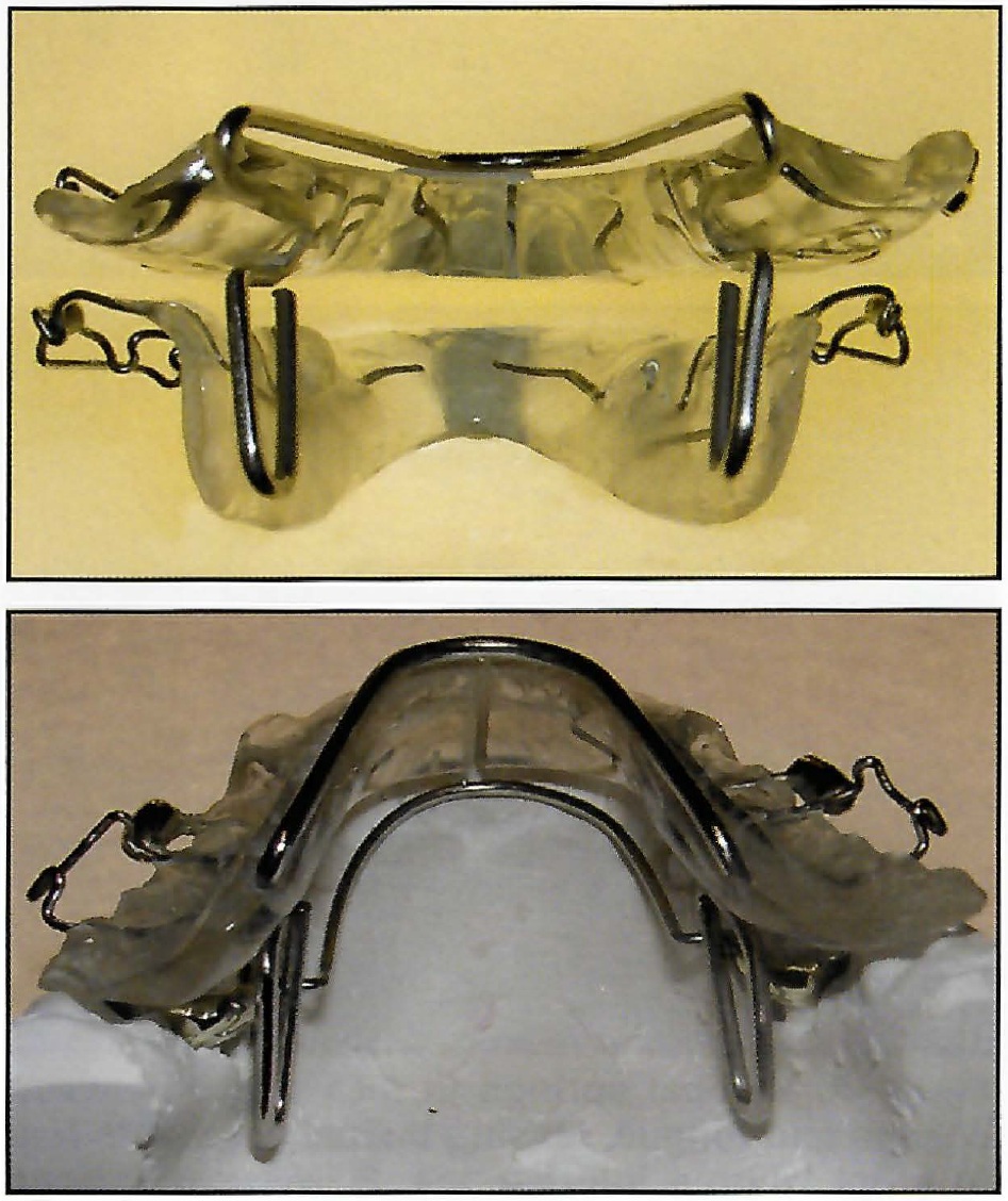
Fig. 3 Vertical springs on maxillary component engage “shoulders” on lower component to produce protrusive mandibular position.
The vertical springs are 14mm long, permitting the protrusive action of the appliance over nearly the full range of mandibular opening. The protrusive action of orthopedic appliances that hold the forward position over a short range of opening is often lost during speech or at night,10 since the majority of children sleep with the mouth open.11 In the Dynamax system, mandibular protrusion is kept to a minimal 3-4mm, allowing the contact between the upper and lower parts of the appliance to act as a stimulus to the musculature in developing an avoidance reflex that will hold the mandible forward. Much of the time there is actually a space between the two components, as the patient will generally hold the mandible farther forward and out of contact. This minimizes the forces acting on the dentition and thus any unwanted dentoalveolar changes. The spring action of the vertical projections acts as a stress breaker, but permits lateral mandibular movements.
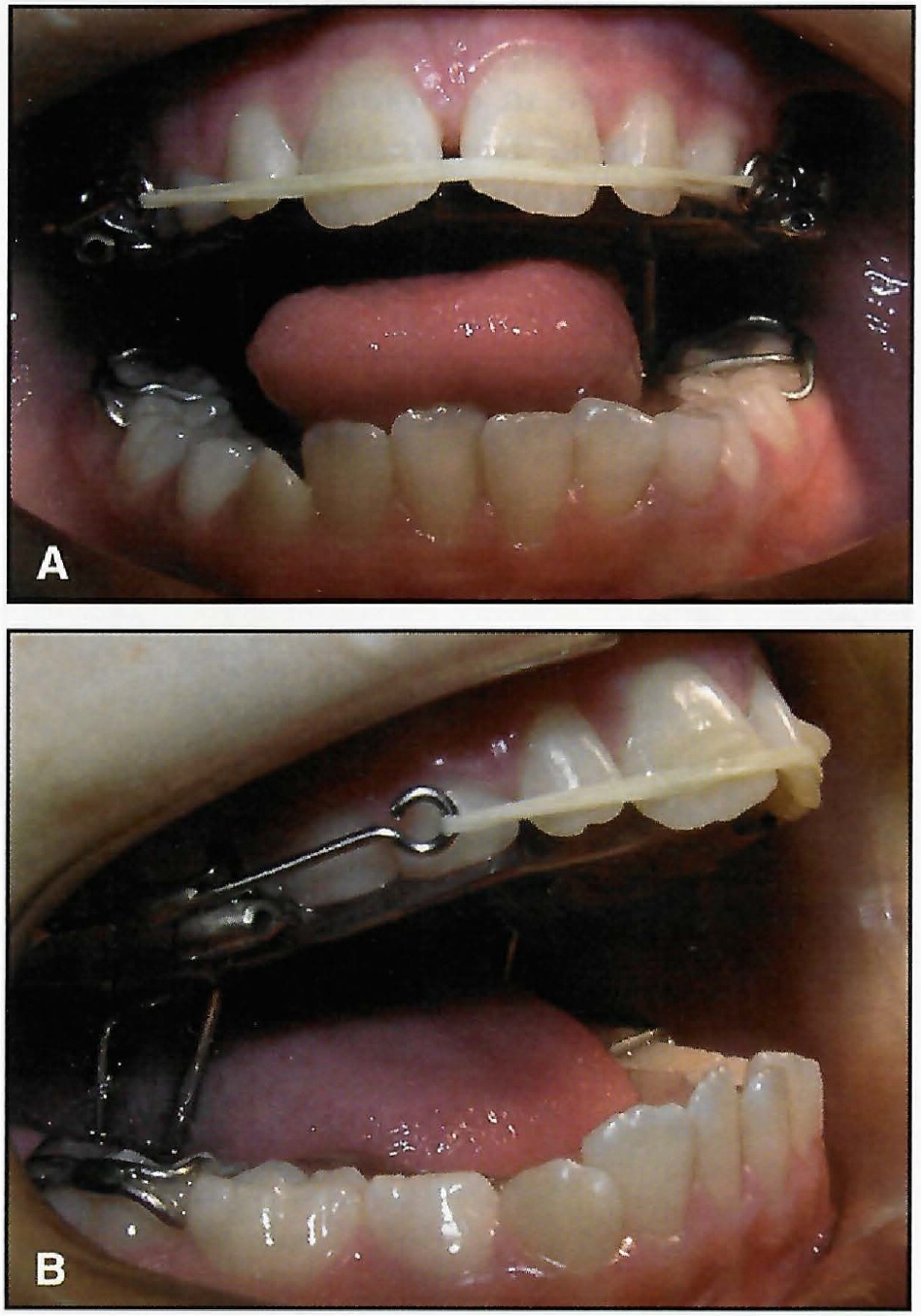
Fig. 4 A. Vertical springs fit into space between cheeks and tongue, leaving buccal segments free to erupt without interference. B. Vertical springs remain in contact with mandibular “shoulders” throughout range of opening to maintain protrusive position of mandible.
4. Occlusal coverage of the upper posterior teeth with a 1mm thickness of acrylic (Fig. 5), which has the following effects:
- Unlocks the occlusion, allowing the mandible to develop forward without interference from the cusps of the posterior teeth.
- Distributes the extraoral forces across all the upper teeth, reducing the pressure on individual teeth to a comfortable level.
- Allows vertical forces to be applied to the maxilla to prevent its normal downward growth and assist in hinging the mandible forward. This promotes advancement of pogonion, in contrast to an opening of the maxillomandibular angle, which results in the chin moving posteriorly.
- Allows eruption of the posterior teeth to be controlled and, if necessary, completely prevented by varying the thickness of the posterior capping up to the width of the interocclusal freeway space. This also has a positive effect on the direction of mandibular growth and, coupled with control of maxillary growth, assists in treatment of high-angle cases. In low-angle cases, the molars are allowed to erupt by keeping the capping to a thickness of 1mm.
5. Anterior torque control with the torquing spring, which lies comfortably flat against the facial surfaces of the incisors (Fig. 6). Excessive palatal tipping of the upper incisors, by trapping the lower incisors, prevents full forward development of the mandible and compromises the balance of the facial profile.12 Avoidance of tipping also reduces the need for angulation in the fixed appliance stage, which thus becomes simpler and quicker.
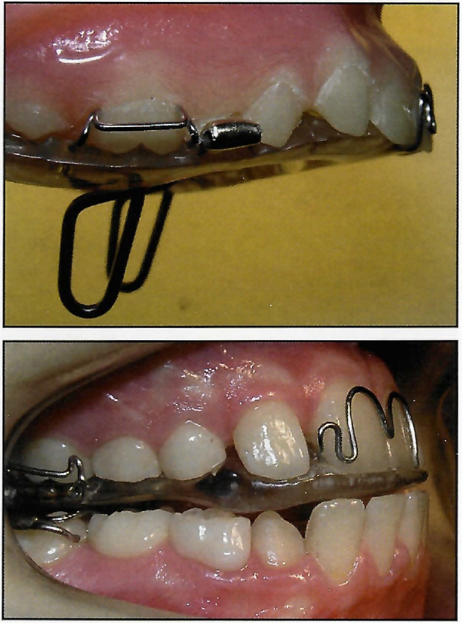
Fig. 5 Acrylic thickness of 1mm over posterior teeth unlocks occlusion and allows application of heavy extraoral force to control maxillary development.
When less torque control is required, 2.5mm acrylic capping of the incisal edges can be used instead of the spring. If the incisors are proclined to start with, the spring and the capping can be left off and the proclination corrected with a facial elastic stretched from canine to canine (Fig. 4).
6. Eruption control of the lower incisors and leveling of the curve of Spee with an anterior biteplane at the level of the incisal edges.
7. Extraoral traction with a posterior high-pull headgear to tubes in the second premolar region, if desired (Fig. 7). Heavy forces of as much as 1,000g per side can control the vertical development of the face13 and, with acrylic coverage of the posterior teeth, can be used without patient discomfort. A safety facebow design is essential whenever extraoral traction is used14 (Fig. 7C).
Mandibular Component
The removable type comprises:
1. Retention with Adams or Crozat clasps on the first molars and, if necessary, on the second deciduous molars. Capping the lower incisors is helpful to improve retention and to control tipping of these teeth (Fig. 8). Where there is a deep curve of Spee and eruption of the posterior teeth is required, the lower incisors should not be capped. A "pull-down" design can also be used, with capping of the buccal segments to provide retention.
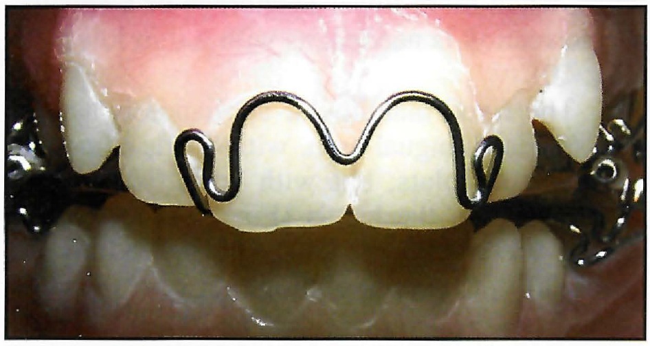
Fig. 6 Anterior torquing spring controls angulation of maxillary incisors and prevents tipping.
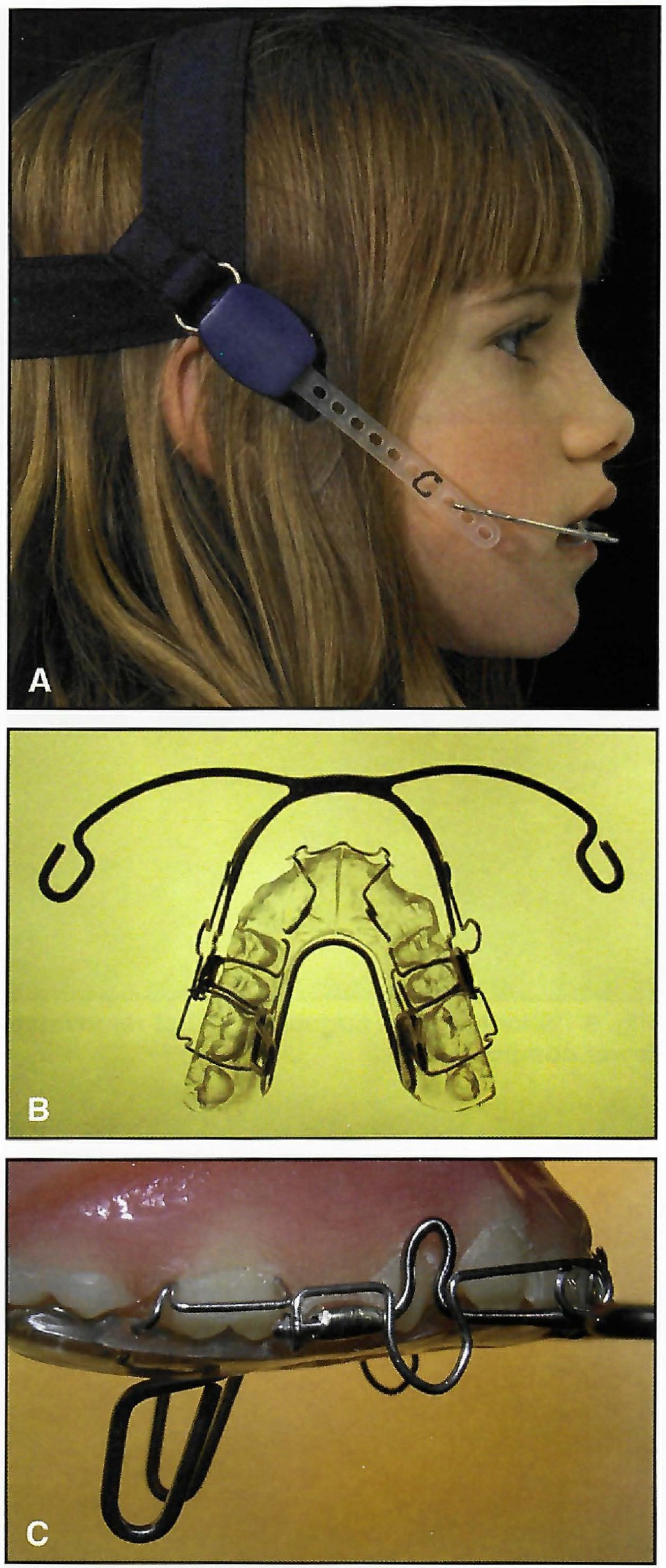
Fig. 7 A. Posterior high-pull headgear attached to facebow. B. Facebow connected to tubes in second premolar region. C. Simple and effective safety catch on Nitom** facebow.
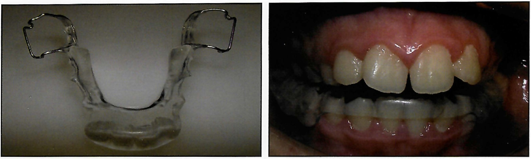
Fig. 8 Capping lower incisors improves retention and controls tipping.
2. An acrylic body extending as far down the lingual of the mandible as possible, without overextending and causing trauma.
3. Acrylic "shoulders", 3mm deep, mesial to the first molars (Fig. 9). These contact the vertical springs on the upper appliance to set the forward position of the mandible.
4. A lip bumper, with the addition of buccal tubes, when more lower anchorage or a soft-tissue correction is needed, as with a thin lower lip (Fig. 10).
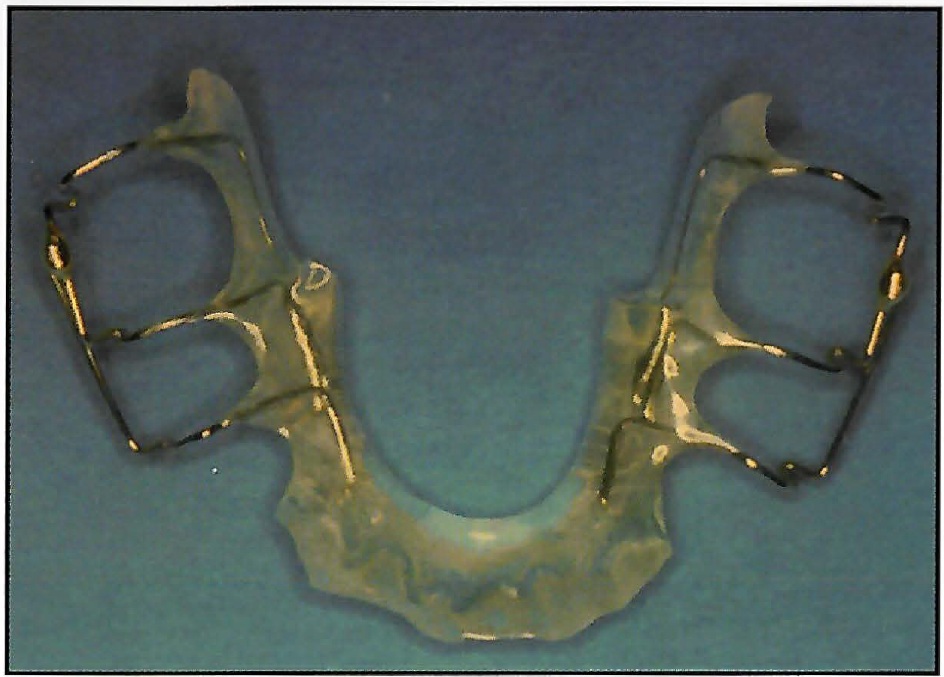
Fig. 9 “Shoulders” in lingual acrylic of removable lower component.
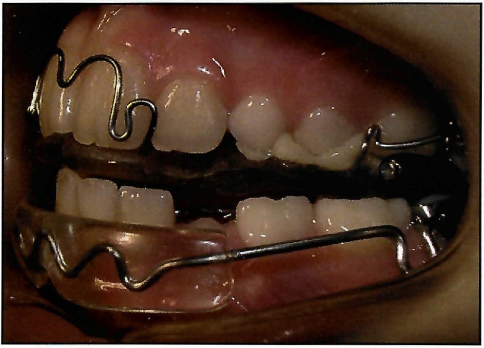
Fig. 10 Lip bumper may be added for soft-tissue control and increased anchorage.
The fixed mandibular appliance is similar to a standard lingual arch, with bands cemented to the first molars, but with 3mm "shoulders" bent mesial to the bands (Fig. 11). The bands should preferably be .010",*** instead of the usual .007", to avoid splitting.
Appliance Construction
Prefabricated wires* are used for both the vertical springs and the expansion element, making laboratory construction uncomplicated (Fig. 12). The manufacturing process includes heat treatment and stress relief to avoid fatigue fractures. Adjustment is simple, usually involving only a width modification, and different sizes are available if needed.
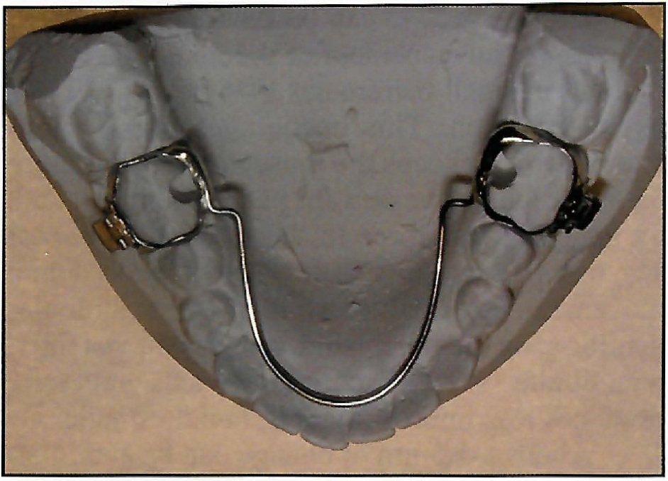
Fig. 11 Fixed lingual arch cemented to bands on lower first molars, with “shoulders” bent into wire mesial to bands.
Good, well-extended alginate impressions are required, along with a hard wax bite in centric occlusion. The lower impression tray should be extended lingually with soft wax to obtain the full depth of the sulcus, and the patient should be instructed to lift and move the tongue to trim the impression. It is important not to overextend the lower appliance, as this will cause discomfort. If a fixed lingual arch is used, the molar bands should be placed first, then transferred to the impression and secured with sticky wax.
In most cases, it is not necessary to provide a construction bite for the technician. The models are simply marked with centric occlusion and do not require mounting on an articulator. The extent of initial forward activation is generally 4mm from centric, and this measurement is readily transferred to the lower model during the standardized construction process to mark the position for the "shoulders" on the lower appliance. The laboratory prescription should indicate the retention desired and any additions such as tooth-moving springs, capping of the lower incisors, or a lip bumper.
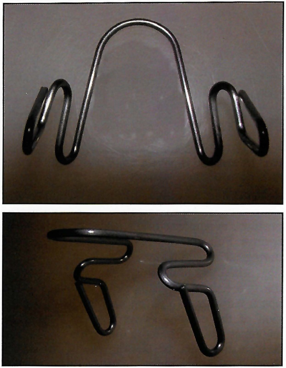
Fig. 12 Prefabricated wire form simplifies appliance construction.
Appliance Delivery
The upper and lower parts are held together to confirm that the vertical springs have been correctly adjusted for lateral width. The fitting surfaces are checked to make sure there are no undercuts or irregularities to interfere with comfort. The lower appliance is tried in the mouth and adjusted if necessary, or the lower lingual arch is cemented into place. When the upper component is inserted, the patient should automatically close comfortably into the protrusive position, in response to the action of the vertical springs. Full-time wear is recommended, except during eating and athletics.
Maxillary expansion is provided by pulling the two halves of the upper appliance 2-3mm apart. Adjustment can be parallel, with expansion of the canines as well as the molars, or asymmetrical, with more posterior expansion. Reactivation can be performed as necessary. Some lateral adjustment of the vertical springs may be required as the maxillary arch widens to avoid making the appliance unwearable or fracturing a vertical spring.
If a headgear is to be worn, it can also be delivered at the first visit. It is usually best, however, to postpone headgear use for a week or two, giving the patient time to adapt to the intraoral appliance.
Mandibular brackets can be bonded with a fixed lingual arch in place, so that leveling and alignment can be carried out during the orthopedic phase (Fig. 13). This can save considerable time during the second stage of treatment, and active intrusion of the lower incisors may be helpful in avoiding an increase in lower facial height. The option of fixing the maxillary component in place is presently under consideration.
Progressive Advancement of the Mandible
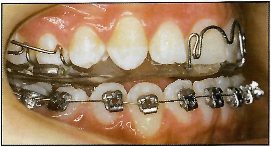
Fig. 13 Bonded brackets used with fixed lingual arch as mandibular component.
The patient's maximum mandibular protrusion (reverse overjet15) should be noted initially so that future growth can be accurately assessed. Progressive advancement of the mandible is carried out in small increments,1,2,5,6 rather than one large activation. This encourages a maximum rate of growth, keeps the musculature supporting the mandible unstressed for patient comfort, and, by applying less force to the lower dentition at any one time, results in less undesirable dental movement.16 A forward shift of the mandibular dentition, on the other hand, reduces the potential mandibular skeletal correction and generally produces less improvement in facial esthetics.
About 1-1.5mm of change can be anticipated every six to eight weeks, assuming reasonable growth and proper appliance wear. At each appointment, the vertical springs are easily adjusted at the chair, using ordinary orthodontic pliers, to maintain the forward position of the mandible. The anterior leg of each spring is gently moved forward 2mm, then the posterior leg is adjusted forward to keep the slope of the anterior leg the same as before (Fig. 14). The slope is checked by sighting across the appliance to the unadjusted spring. An alternative method--adding acrylic to the "shoulders" of the removable lower appliance--is more time-consuming.
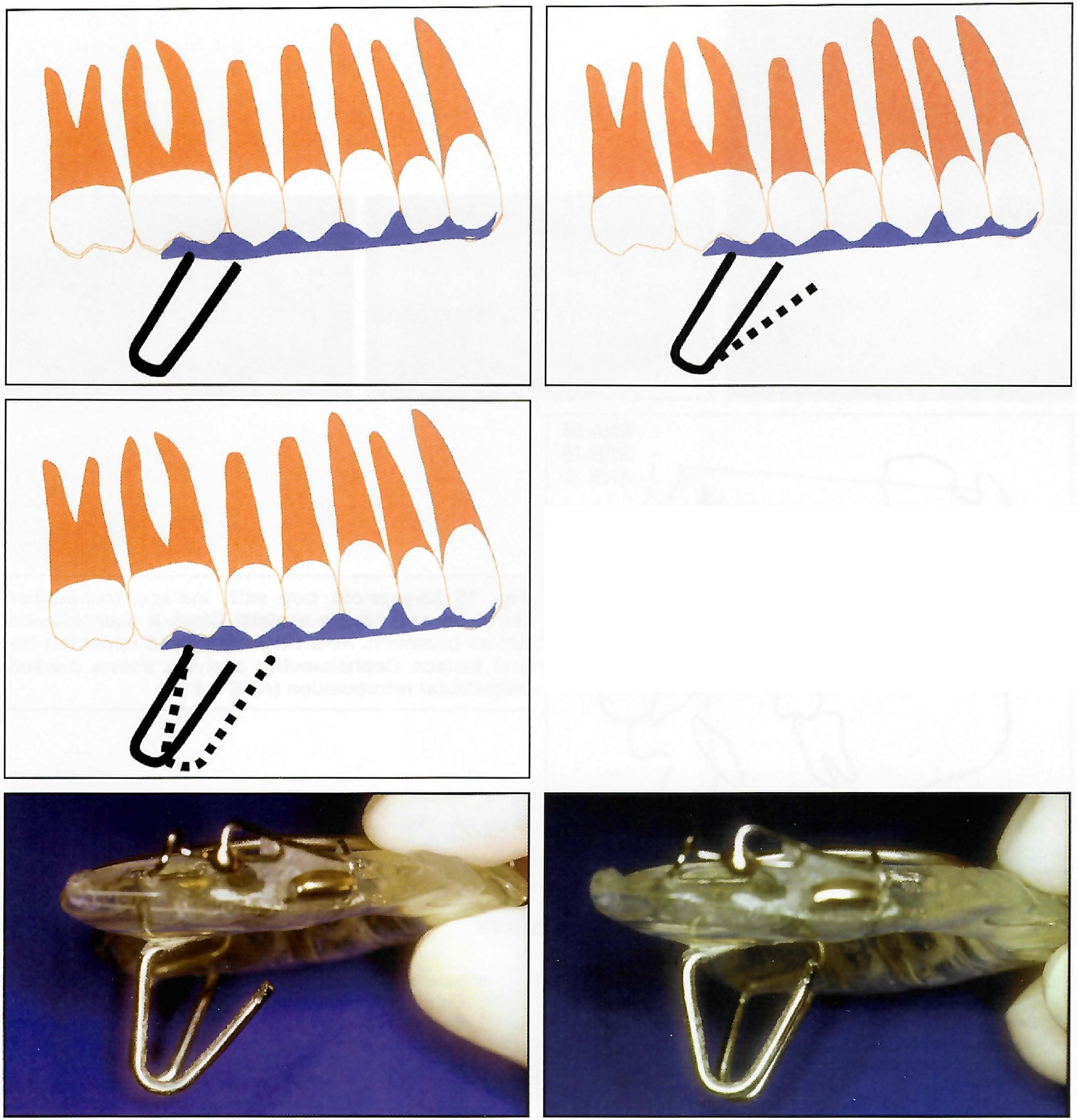
Fig. 14 Vertical springs are advanced every six to eight weeks. Front leg is bent forward with plier, then rear leg. Sighting across to unadjusted spring allows original slope of spring to be maintained, so that new position is parallel to original.
As the patient develops an avoidance reflex to the springs, he or she will frequently be unaware that reactivation has taken place. The appliance should not be reactivated again, however, until further growth has occurred. When the patient habitually holds the mandible well forward of contact with the springs, it may be feasible to dispense with daytime wear of the mandibular removable appliance.
Conclusion
The Dynamax system can be used to correct the skeletal Class II malocclusion efficiently and predictably at any stage in the dental development of a growing patient (Figs. 15 and 16). Laboratory construction, appliance delivery, and reactivation are simple and rapid procedures. The appliance is robust, comfortable, and unobtrusive, and interferes minimally with speech.
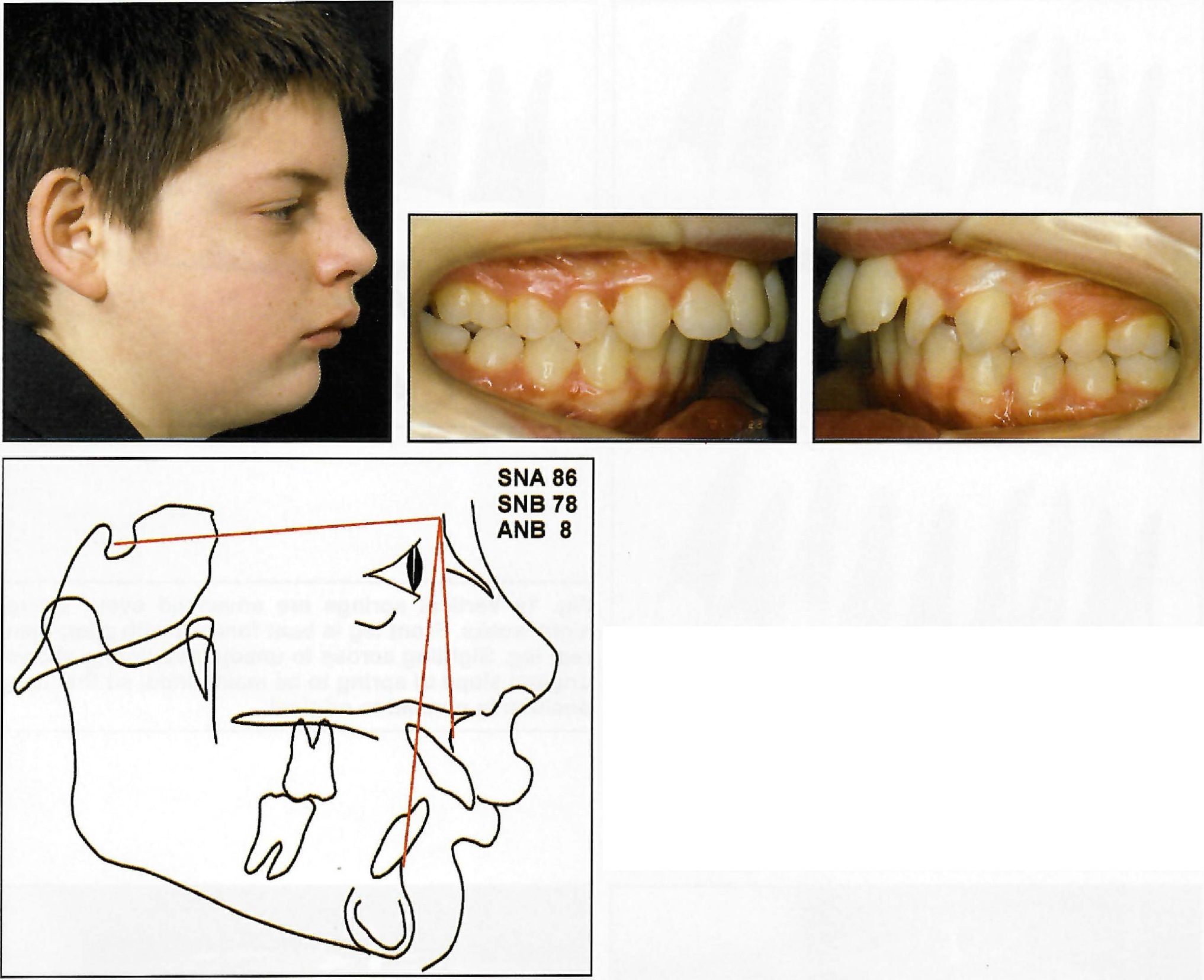
Fig. 15 13-year-old boy with marked mandibular retrusion and severe skeletal Class II malocclusion before treatment. Note severely rotated upper left lateral incisor. Cephalometric analysis shows marked mandibular retroposition (ANB = 8°).
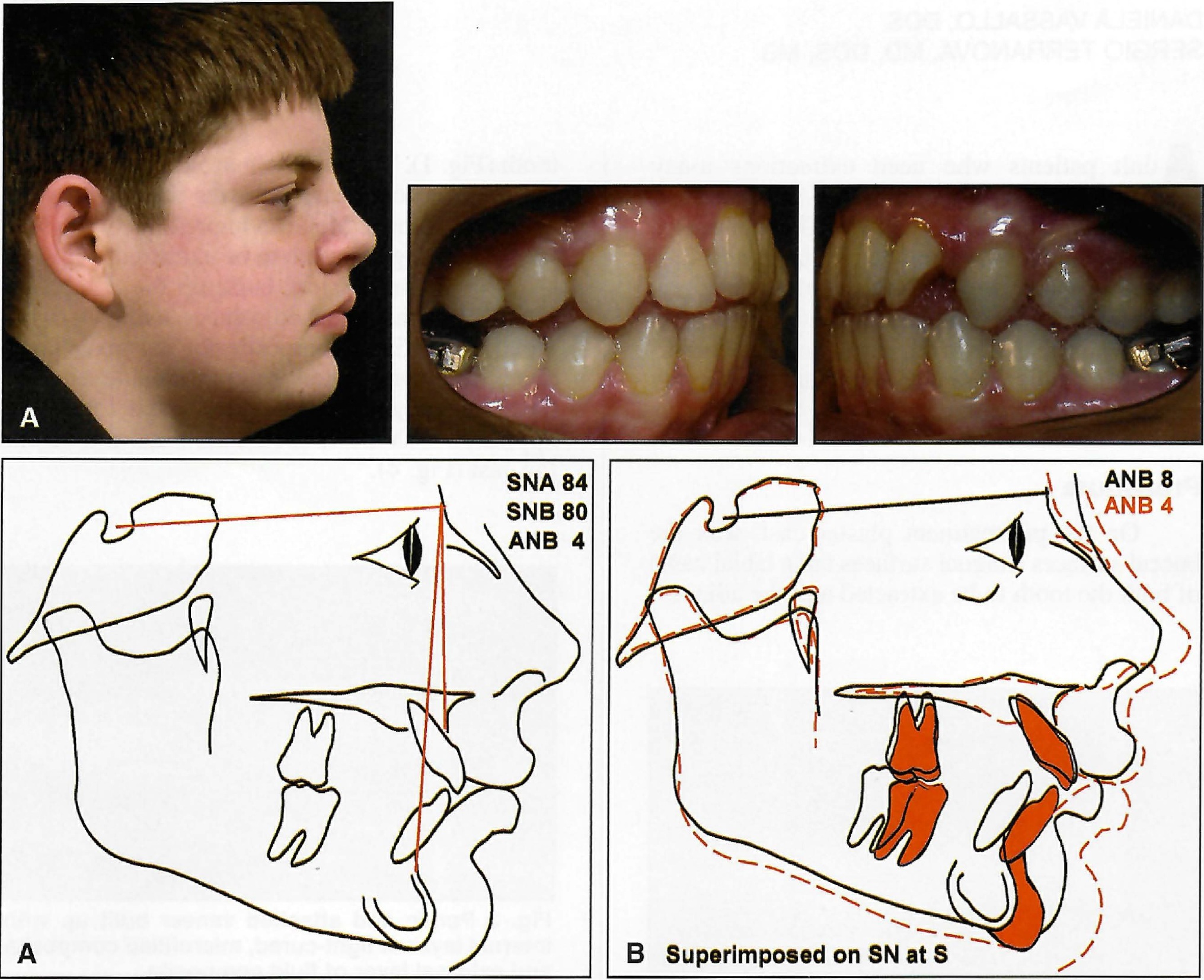
Fig. 16 A. After 18 months of orthopedic treatment with Dynamax appliance. Treatment time was longer than usual because of need to move rotated upper left lateral incisor out of interference with lower incisors. Facial harmony and normal soft-tissue function were established. With ANB reduced by 4°, underlying skeletal disharmony was corrected, allowing lower lip to function in front of upper incisors and improving esthetics of facial profile. Occlusion was fully corrected in sagittal direction, but canine interference prevented full integration of posterior teeth. Patient is now ready for Phase II therapy with fixed appliances to fully align dentition and establish ideal occlusion. B. Superimposition on SN at S shows no forward growth of maxilla in response to heavy extraoral traction. Upper incisors have been controlled by torquing spring and show almost no tipping. Mandible has grown forward strongly to correct skeletal Class II pattern.
Placing the protrusive mechanism at the sides of the teeth avoids occlusal interference and an unplanned increase in lower facial height. Posterior tooth contact is maintained throughout the orthopedic phase, allowing a well-coordinated and integrated dentition to develop and improving the transition to second-phase fixed appliance treatment.
FOOTNOTES
- *Dynamax (UK) Ltd., 4 Queen Anne St., London W1G 9LQ, England; www.dyn-max.com.
- **Ortho-Kinetics, 1611A S. Melrose Drive, Vista, CA.
- ***TP Orthodontics, 100 Center Plaza, LaPorte, IN 46350, or Ormco/“A” Company, 1717 W. Collins Ave., Orange, CA 92867.
REFERENCES
- 1. Bass, N.M.: Dento-facial orthopaedics in the correction of Class II malocclusion, Br. J. Orthod. 9:3-31, 1982.
- 2. Bass, N.M.: Orthopedic coordination of dentofacial development in skeletal Class II malocclusion in conjunction with edgewise therapy, Parts I and II, Am. J. Orthod. 84:361-383, 466-490, 1983.
- 3. Clark, W.J.: The Twin Block traction technique, Eur. J. Orthod. 4:129-138, 1982.
- 4. Clark, W.J.: Twin block functional therapy, in Applications in dentofacial orthopaedics, Mosby-Wolfe, London, 1995, pp. 20-22, 76, 134.
- 5. Bass, N.M.: Bass Orthopedic Appliance System, Part I: Design and construction; Part II: Diagnosis and appliance prescription; Part III: Case management, J. Clin. Orthod. 21:254-265, 312-320, 384-394, 1987.
- 6. Bass, N.M.: Update on the Bass Appliance System, J. Clin. Orthod. 28:421-428, 1994.
- 7. Brennan, M.M. and Gianelly, A.A.: The use of the lingual arch in the mixed dentition to resolve incisor crowding, Am. J. Orthod. 117:81-85, 2000.
- 8. Bass, N.M.: Innovation in skeletal II treatment including effective incisor root torque in a preliminary removable appliance phase, Br. J. Orthod. 3:223-230, 1976.
- 9. McDonagh, S.; Moss, J.P.; Goodwin, P.; and Lee, R.T.: A prospective optical surface scanning and cephalometric assessment of the effect of functional appliances on the soft tissues, Eur. J. Orthod. 23:115-126, 2001.
- 10. Bass, N.M.: Chin support for orthopedic and functional appliances, J. Clin. Orthod. 30:110-114, 1996.
- 11. Sander, F.G.: Der Einfluss herausnehmbarer kieferortopädischer Apparate auf den Nachtschlaf der Patienten, Fortschr. Kieferorthop. 43:57-63, 1982.
- 12. Bass, N.M.: The aesthetic analysis of the face, Eur. J. Orthod. 13:343-350, 1991.
- 13. Teuscher, U.: An appraisal of growth and reaction to extraoral anchorage, Am. J. Orthod. 89:113-121, 1986.
- 14. Samuels, R. et al.: A clinical evaluation of a locking orthodontic facebow, Am. J. Orthod. 117:344-350, 2000.
- 15. Petit, H.P. and Chateau, M.: The K test and the condylar test, J. Clin. Orthod. 18:726-732, 1984.
- 16. Falck, F. and Frankel, R.: Clinical relevance of step-by-step mandibular advancement in the treatment of mandibular retrusion using the Frankel appliance, Am. J. Orthod. 96:333-341, 1989.
-
 DR. BASS
 -
 DR. BASS
Dr. Neville Bass is Director of Dynamax (UK) Ltd. and in the private practice of orthodontics at 4 Queen Anne St., London W1G 9LQ, England; e-mail: drnbass@aol.com. Dr. Anton Bass is in the private practice of general dentistry in London.