Where Teeth Should Be Positioned in the Face and Jaws and How To Get Them There
Contrary to conventional thought, the optimum position of the teeth in the face should be determined by the position of the maxillary incisors, rather than the mandibular incisors.
To achieve optimum esthetics and stability, Tweed advocated placing the mandibular incisors upright over basal bone (in other words, at 90º to the mandibular plane, plus or minus a small variation depending on the mandibular plane angle, to maintain an FMIA of 65-68º), and positioning the maxillary incisors with ideal overbite, overjet, and interincisal angulation relative to the mandibular incisors.1 Thus, Tweed's decision on where the teeth should be positioned in the face was predicated solely on the angulation of the mandibular incisors. Since angular measurements do not necessarily reflect anteroposterior positions, the Tweed Triangle has serious limitations.
Ricketts stated, "We all accept that Tweed was correct in building his plan around the lower incisor segment".2 Consequently, the Ricketts analysis was also built around mandibular incisor position. He related the mandibular incisor to the APo plane, which automatically changes the position of the incisor on the mandible as the jaw relationships change (as measured by the convexity). Initially, Ricketts suggested placing the mandibular incisor 1mm ahead of the APo plane (with a range of -1mm to +3mm) and at an angle of 22º to it. The maxillary incisor was positioned with a 2-2.5mm overbite and overjet and an interincisal angle of 130º. However, later studies of untreated patients, average age 55, revealed a more protrusive range of -1mm to +6mm (with a mean of +2.5mm). This does not mean that the teeth can be positioned within this 7mm range on most patients and yield satisfactory esthetics. There are some patients who need the -1mm position, and others who need the +6mm position. In any case, Ricketts positions the teeth in the face by placing the mandibular incisors relative to the APo plane.
Similar articles from the archive:
- JCO INTERVIEWS Thomas D. Creekmore, DDS, on Treatment Mechanics November 1996
- JCO ROUNDTABLE Diagnosis and Treatment Planning September 1992
- Teeth Want to Be Straight November 1982
Steiner recommended positions for both maxillary and mandibular incisors in the face.3 Those positions were determined relative to lines NA and NB, and they varied according to the jaw relationships as indicated by the ANB angle (Fig. 1). A 2º ANB was considered ideal, with the maxillary incisors at 22º and 4mm anterior to line NA, and the mandibular incisors at 25º and 4mm anterior to line NB. The maxillary incisors were repositioned 1º and 1mm to NA, and the mandibular incisors were repositioned 1º and only ¼mm to NB, for each degree of ANB change from the ideal. For example, in a patient with a 6º ANB at the completion of treatment, the maxillary incisors were to be at 18º and 0mm to NA, and the mandibular incisors at 29º and 5mm anterior to NB; in other words, the maxillary incisors would be 4mm more lingual than in the ideal case, and the mandibular incisors would be only 1mm advanced from the ideal. For another patient finishing with a -1º ANB, the maxillary incisors were to be at 25º and 7mm to NA and the mandibular incisors at 22º and 3.25mm to NB; thus, the maxillary incisors would be 3mm advanced from the ideal, and the mandibular incisors would be only .75mm lingual to the ideal. As ANB varied from -1º to +6º, maxillary incisor position changed by 7mm to NA, while mandibular incisor position changed by only 1.75mm to NB. Again, according to the Steiner analysis, positioning teeth in the face depends largely on the mandibular incisors. Their position remains fairly constant, but the position of the maxillary incisors varies a great deal to fit with the mandibular arch.
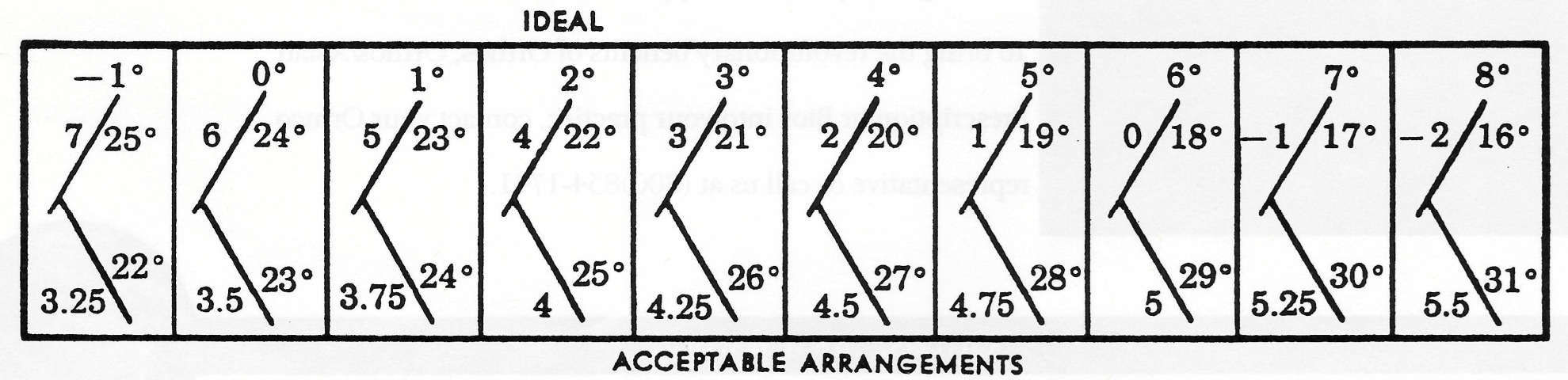
Fig. 1 Recommended tooth positions in Steiner analysis.
Actually, relating the mandibular incisor to NB does not truly reflect the position of the incisor on the mandible, because B point and the entire dentition can be located far labially or lingually on the mandible. Holdaway modified the Steiner analysis by suggesting that the mandibular incisors be placed forward of NB by the same number of millimeters that pogonion was forward of NB.
Is the premise that mandibular incisor position determines optimum stability and facial esthetics valid? Is that what is found to occur naturally? The answer is "no", as the cases in this article will demonstrate.
Incisor Positions and Jaw Relationships
Casko measured 79 cases with ideal occlusions and acceptable esthetics from Tweed's 1954 sample, and found a wide range of incisor positions and jaw relationships.4 Mandibular plane angle varied from 15º to 41º, facial angle from 79º to 95º, maxillary incisor to SN from 93º to 120º, and mandibular incisor to APo from -4mm to +6mm with a mean of 2.2mm. Casko stated, "These values are all normal in the faces in which they were found. Many current systems of cephalometric evaluation would classify many of these patients as abnormal." While the mean ANB angle was indeed 2º, the range was -3º to +8º, encompassing patients who would be classified as Class I, Class II, and Class III skeletal patterns; yet they all had Class I occlusions with good esthetics. This suggests that our current description of skeletal patterns is flawed. A more accurate observation is that normal skeletal patterns may have ANB angles of -3º to +8º and be associated with Angle Class I, Class II, or Class III occlusions.
In a cephalometric analysis of 125 untreated adults with ideal facial and occlusal relationships, McNamara found essentially the same variations in incisor positions and jaw relationships.5 Additionally, in 44 males, A point to nasion perpendicular ranged from -6mm to +9mm--a 15mm range--with a mean of +1mm; and pogonion to nasion perpendicular ranged from -8mm to +10.5mm--an 18.5mm range--with a mean of -.5mm. McNamara recommended differential treatment of Class II malocclusions depending on the protrusion or retrusion of the maxilla and/or mandible relative to their average nasion perpendicular positions. How ever, normally occurring skeletal patterns and occlusions can be far from the mean, and correcting toward the mean is not always possible or desirable.
McNamara concluded, "This study presents dentofacial norms for males and females with ideal occlusal and facial relationships. It should be stressed that in each individual, infinite combinations are possible to arrive at a face that is well balanced with an occlusal relationship that is ideal. The purpose of establishing cephalometric norms should not be to create 'targets' for individual treatment but to have guides for the clinical assessment of the patient. The final diagnosis and treatment plan must rely on a number of other factors that are beyond the information obtained from a radiograph." This conclusion seems to indicate that teeth are positioned in a random manner in different jaw relationships for no apparent reason. Perhaps we should use average targets for average patients and develop other targets for those who differ from the average.
Both Solow6 (writing about dentoalveolar compensation) and Creekmore7 documented how teeth migrate on the jaws to maintain a constant occlusal relationship, even though the maxilla and mandible are growing differently relative to each other in the horizontal, vertical, and transverse dimensions. This compensatory mechanism explains how and why the positions of the teeth on the jaws vary as the jaw relationships vary.
Andrews, in developing the Straight-Wire Appliance*, measured crown torques relative to the Andrews plane and found the average maxillary and mandibular central incisors to have inclinations of +7º and -1º, respectively.8 The Andrews plane is about the same as the maxillary and mandibular archwire planes, which do not necessarily parallel each other but vary from each other and the occlusal plane as overbite varies.
Ross and colleagues documented how incisor torque varied as the cant of the occlusal plane changed, without a subsequent change in the incisor angulation relative to the cranial base.9 Creekmore developed an Incisor Torque Template** to measure maxillary and mandibular incisor crown torques relative to their archwire planes on the cephalogram or cephalometric tracing10 (Fig. 2). The torques are measured tangent to a point 4.5mm and 4mm from the incisal edges of the maxillary and mandibular incisors, respectively.
Radney Analysis
In his award-winning presentation of cases to the Texas Tweed Study Group, Radney noted that the maxillary incisors were centered in the premaxilla and that the incisal edges of the mandibular incisors were consistently aligned with line NA regardless of the jaw relationship.11 Cases in which the jaw relationships differ from average demonstrate that a pattern or correlation does exist between tooth positions and jaw relationships. This pattern is demonstrated by analyzing cases in which the jaw relationships differ considerably from average.
In a case from Casko's study with low occlusal (1º) and mandibular plane (14º) angles, the mandible is well forward of the maxilla, as indicated by a -1º ANB and a -6mm convexity4 (Fig. 3). The mandible is much more prognathic than a -1º ANB would indicate, because B point is so far back on the mandible. The mandibular incisors are at 7º and 0mm to NB and 19º and -5mm to the APo line, with a torque of -12º to the mandibular archwire plane. Pogonion is 10mm forward of the NB line, producing a Holdaway difference of -10mm; in other words, the mandibular dentition is far back on the mandible (Fig. 3C). But the mandibular incisors are aligned with line NA, as Radney observed.
According to the Ricketts analysis, the maxillary incisors are quite retrusive and upright relative to the APo plane. However, they are at 21º and 4mm to NA (Fig. 3A), centered in the premaxilla, and properly angulated relative to the cranial base--in other words, ideally positioned in the maxilla. Due to the cant of the occlusal plane (1º), the incisors have a -4º torque to the maxillary archwire plane (Fig. 3A). When anteroposterior jaw relationships differ greatly from average, measurements of maxillary and mandibular incisors to the APo plane misrepresent their positions within the jaws.
The position of the maxilla and the maxillary teeth can be camouflaged by the relative position of the mandible. The maxillary arch will appear retrusive with prognathic mandibles (Fig. 3) and protrusive with retrognathic mandibles (Fig. 4).
A case from Casko's study with high occlusal (16º) and mandibular plane (40º) angles shows a 5º ANB and a 6mm convexity4 (Fig. 4). The mandibular incisors are well forward on the mandible (Fig. 4C), at 32º and 8mm to NB and 27º and 5mm to APo. The Holdaway difference is +9mm. Their torque is 3º. However, they are only 1mm anterior to NA, agreeing with Radney's observation. The maxillary incisors are at 24º and 4mm to NA and 33º and 8mm to APo. The teeth are much farther forward than either the Ricketts or Steiner analysis would call for, but the maxillary incisors are centered in the premaxilla (Fig. 4A) and properly related to the cranial base.
In these two Casko cases, the high-mandibular-plane-angle patient had a high ANB, and the low-mandibular-plane-angle patient had a low ANB. This is usually true, but not always. It is the anteroposterior jaw relationship--not the vertical relationship--that requires the variation in tooth position.
As the mandible is positioned farther back relative to the maxilla, the mandibular incisors become more and more protrusive. Conversely, as the mandible is positioned farther and farther forward relative to the maxilla, the incisors become more and more retrusive. Maxillary incisor positions in the maxilla do not vary as much as mandibular incisor positions on the mandible.
This is exactly opposite to the Tweed and Steiner analyses and somewhat contrary to the Ricketts analysis. The goals of these analyses would retract the teeth too far in the face in high-ANB, high-convexity cases. Extractions could be required to reach the goals, possibly leading to a flattening of the face. On the other hand, the goals for low-ANB, low-convexity cases would indicate more nonextraction treatment, which can produce too protrusive a result.
The current nonextraction fad puts too much blame for flattening faces on the extraction of teeth. Some of the blame should be placed on an absence of goals or on the use of average goals for non-average patients. Treatment outcomes are also related to an understanding of the capabilities and limitations of an individual clinician's treatment mechanics.
Where To Position the Teeth in the Face and Jaws
The following three cases are from Creekmore's unpublished study of 27 individuals in the McNamara sample of patients with ideal occlusions and facial esthetics.5 They were selected to illustrate where teeth should be positioned in the face and jaws for varying skeletal patterns.
Figure 5A shows an ideal (average) skeletal pattern. The Tweed Triangle, Steiner analysis, Ricketts analysis, Radney analysis, Andrews incisor torque values, and everybody else's analyses are "right on". This pattern has a 2.5º ANB and a 1.5mm convexity. The maxillary incisors are at 4mm to NA, and the mandibular incisors at 4mm to NB. The Holdaway difference is 1.5mm, and the mandibular incisors are at 0mm to the APo plane, approximating the ANB angle and the convexity. The mandibular incisor is on the NA line, as Radney suggests. Andrews torques for the maxillary and mandibular incisors are 6º and -3º, respectively.
Figure 5B shows a case with a low ANB (0º and a -2mm convexity. The maxillary and mandibular incisors are in positions recommended only by Radney. The maxillary incisors are centered in the premaxilla at 4mm to NA. The mandibular incisors are retruded, as indicated by a -2mm Holdaway difference and a -2mm relationship to APo. Both measurements equal the convexity. Again, the mandibular incisor is on the NA line. Andrews torques for the maxillary and mandibular incisors are 2º and -14º respectively.
Figure 5C shows a high ANB (5º and a 4.5mm convexity. The maxillary incisor, at 5mm to NA, is 1mm farther forward than "ideal"; the mandibular incisor, at 9mm to NB, is much farther forward on the mandible, but still on the NA line. The Holdaway difference is 6.5mm, and the mandibular incisor is at 4mm to the APo plane, both again approximating the ANB angle and the convexity. Andrews torques for the maxillary and mandibular incisors are 16º and -4º respectively, due to the 22º cant of the occlusal plane.
It is obvious from these three examples that cephalometric goals predicated on averages, "ideal", or "normal" do not work for cases that differ appreciably from average. One Straight-Wire Appliance prescription cannot fit all skeletal patterns. In deciding where the teeth should be positioned in such cases, I recommend the following analysis modifications:
Simplified Radney Analysis
Position the maxillary incisors at 5mm ± 2mm and 22º ± 5º to NA for all skeletal patterns. The measurements increase as the ANB angle decreases, and decrease as ANB increases.
Position the mandibular incisal edges at .5mm ± 2mm to NA and 25º ± 5º to NB , with values decreasing as ANB decreases and increasing as ANB increases. Changes in the jaw relationships during treatment will change the incisor-to-NA position and should be anticipated in the treatment plan.
If an ideal overbite and overjet have been established during treatment and the incisal edge of the mandibular incisor is aligned with NA, the maxillary incisor must be well positioned in the maxilla and the mandibular incisor must be properly positioned on the mandible to compensate for the difference in the jaw relationship.
Modified Steiner Analysis
The maxillary incisors will be ideally positioned in the maxilla if the mandibular incisors are positioned so that the Holdaway difference equals ANB at the end of treatment. This is not always accurate, because of the influence on ANB of large variations in the location of B point.
Modified Ricketts Analysis
To achieve an ideal position of the maxillary incisors, place the mandibular incisors in a position relative to APo that equals the final convexity. For example, the mandibular incisor would be at 6mm to APo for a 6mm convexity. Remember that APo is not a fixed line. It changes with growth and treatment as the jaw relationships change, similarly to the mandibular-incisor-to-NA line. In turn, this will cause a change in the mandibular-incisor-to-APo measurement, even with no movement of the incisor on the mandible.
How To Get Them There
I was taught by Dr. Fred Schudy that the biggest money savers in orthodontic practice come from the time spent planning a workable solution to the patient's problem. Treatment planning starts at the initial examination, where a subjective evaluation is made of the patient's problems--including facial and dental esthetics and maturational status as it relates to growth--and potential solutions. A detailed objective evaluation of the patient's diagnostic records follows, to formulate the best treatment plan and individualized appliance prescription for that patient.
The easiest task for the clinical orthodontist is to align the maxillary teeth on the maxilla and the mandibular teeth on the mandible. That is easily accomplished with or without extractions, with or without favorable growth, and it requires no patient compliance other than appearing for appointments and not destroying the appliances.
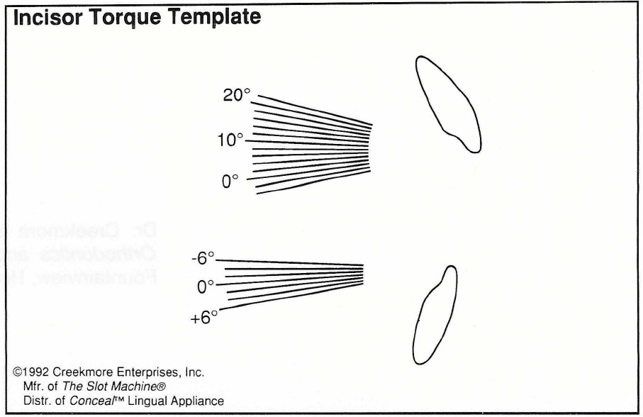
Fig. 2 Incisor Torque Template.
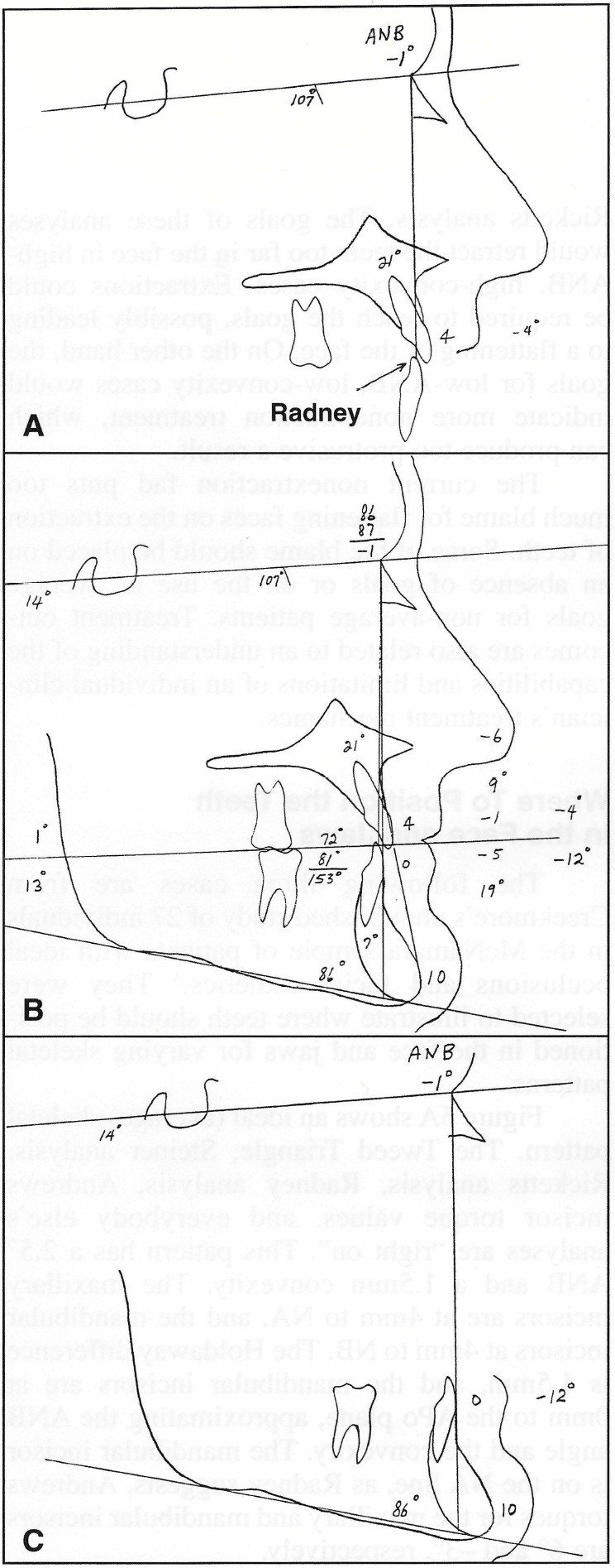
Fig. 3 Simplified Radney analysis of patient from Casko4 study with low occlusal and mandibular plane angles. A. Due to 1 ° cant of occlusal plane, maxillary incisors have -4° torque to maxillary archwire plane. B. Entire analysis. C. Mandibular dentition is well back on mandible, but incisors are aligned with NA.
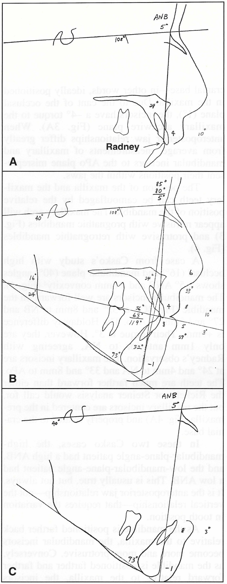
Fig. 4 Simplified Radney analysis of patient from Casko4 study with high occlusal and mandibular plane angles. A. Maxillary incisors are centered in premaxilla and properly related to cranial base. B. Entire analysis. C. Mandibular incisors are far ahead of NB, but in stable, esthetic position 1 mm anterior to NA.
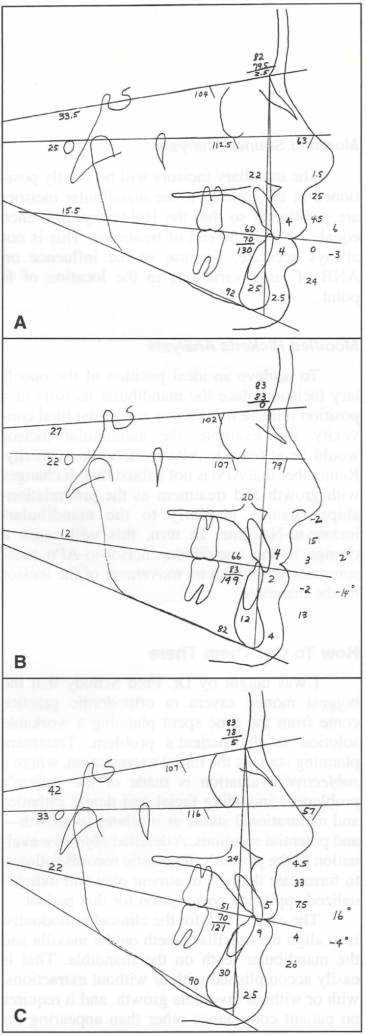
Fig. 5 A. Average skeletal pattern. B. Low ANB and convexity. C. High ANB and convexity.
The most difficult task is to establish proper overbite and overjet with the jaws in centric relation. That usually does require patient cooperation, favorable growth, and proper treatment planning . Many orthodontists have turned to early treatment to make "orthopedic corrections" while the patient is still growing and presumably more cooperative. Appliances such as the Herbst***, Jasper Jumper†, and Hilgers Pendulum‡ reduce the requirement for patient compliance, but may not deliver the teeth to the best positions for optimum esthetics and stability.
An alternative way to reduce the need for compliance is by strategic extraction of certain teeth other than four first bicuspids. This helps develop proper intra-arch anchorage for positioning the teeth on the jaws, and proper interarch anchorage to correct the overbite and overjet with the mandible in centric relation. Strategic extraction does not entirely eliminate the need for patient cooperation, but greatly reduces it, since it is mechanically easier to obtain a better result by controlling reciprocal anchorage.
Case 1
The patient was a mature 13-year-old female with a straight profile, a Class I malocclusion, and a maxillary midline shift to the left, with the left canine blocked out (Fig. 6A). The mandibular canines were also blocked out, and there was a 7mm arch-length discrepancy. Surprisingly, she had a Class II skeletal pattern that I could not see by just looking at her face. She had a 6º ANB, a 5mm convexity, a high mandibular plane angle (43º) with an obtuse gonial angle, and a high occlusal plane angle (23º). The maxillary incisors were at 7mm and 18º (upright) to NA, yet their torque was 14º to the maxillary archwire plane. The mandibular incisors were at 5mm to the APo plane and 9mm to NB, and Po was at 1mm to NB. There was an 8mm Holdaway difference. Mandibular incisor crown torque was 8º to the mandibular archwire plane.
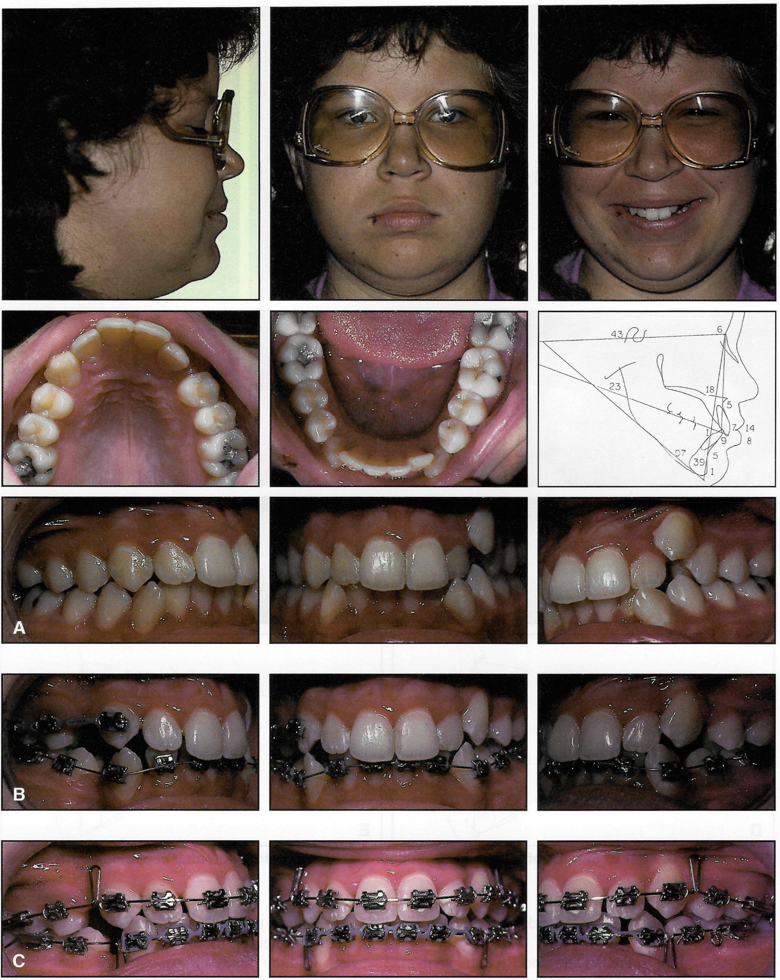
Fig. 6 A. Mature 13-year-old female with high ANB angle and Class I malocclusion before treatment. B. After five months of treatment with sectional archwires, mandibular incisors bonded and .018" Nitinol archwire placed. Maxillary left canine spontaneously drifted distally into extraction site. C. Remaining spaces closed with .017" x .022" closing-loop archwires, followed by .018" x .025" finishing wires (continued in next image).
According to the Steiner and Ricketts analyses, the patient's teeth were quite protrusive. These analyses would have required extraction of all four first bicuspids plus maximum anchorage control to reach their goals. However, the modified Steiner, modified Ricketts, and simplified Radney analyses showed the mandibular incisors to be only 1mm protrusive on the mandible and the maxillary incisors only 2-3mm protrusive to NA. Our goal, then, was to retract the mandibular incisors 1mm and the maxillary incisors about 3mm in this non-growing patient.
Treatment Planning (How To Reach Your Goal)
How much do teeth anterior and posterior to extraction sites move with reciprocal intra-arch mechanics during extraction site space closure? Is it predictable?
Rule of thumb: Ordinarily, when mandibular first bicuspids are extracted, you can expect the posterior teeth to come forward about one-third of the space (about 2.5mm on each side), leaving two-thirds of the space (about 5mm on each side) for correction of crowding and for incisor retraction.
Extracting the mandibular first bicuspids in this case would therefore provide 10mm of space, of which 7mm would be used to relieve the crowding. The remaining 3mm would be used to retract the anterior teeth 1.5mm, positioning them within .5mm of our goal.
Therefore, the treatment plan was to extract all four first bicuspids and close the spaces using sectional and closing-loop archwires with an .018" X .025" Uni-Twin†† appliance (Figs. 6B,C). No extraoral anchorage would be required.
Results
The 6º ANB angle and the 5mm convexity remained unchanged. The maxillary incisors were retracted 3mm and intruded 2mm, finishing at 4mm to NA with a torque of 10º to the archwire plane (Fig. 6D). The mandibular incisors were retracted 2mm and intruded 1mm, finishing at 7mm to NB, -1º torque to the archwire plane, and -1mm to NA, with a Holdaway difference of 6mm. Facial esthetics were optimum for this skeletal pattern, and the teeth were positioned in the face according to the modified Steiner, Ricketts, and Radney analyses. No jaw changes occurred in this non-growing patient (Fig. 6E). Treatment time was 27 months. The rule of thumb was accurate.
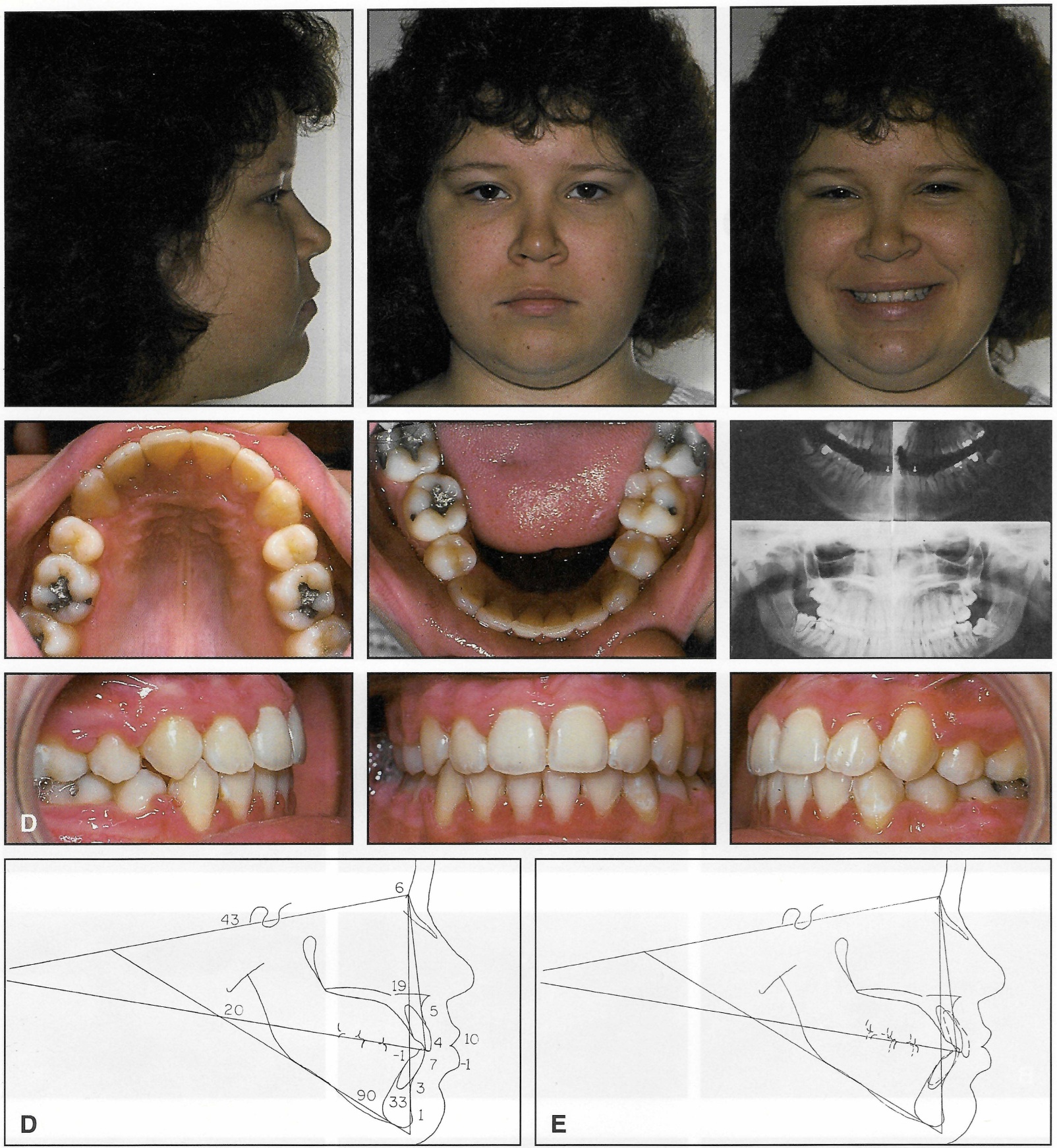
Fig. 6 (cont.) D. After 27 months of treatment. E. Superimposition of before-and-after cephalometric tracings.
Case 2
This mature 16-year-old female had a skeletal pattern opposite to that of Case 1 (Fig. 7A). She had a short lower face with a prominent soft-tissue chin. Her chief complaint was that her anterior teeth seemed protrusive when she smiled. She had a half-Class II malocclusion, a moderate overbite, and mild maxillary and mandibular arch-length discrepancies. The cephalometric tracing showed a low mandibular plane angle (25º), a low occlusal plane angle (12º), a 1º ANB, and a -2mm convexity. The mandibular incisors were 3mm anterior to NA and 2mm to APo. The incisors were at 5mm to NB, and pogonion was at 5mm to NB, for a 0mm Holdaway difference. The maxillary incisors were at 8mm and 31º to NA. The maxillary and mandibular incisor crowns had torques of 12º and 10º, respectively.
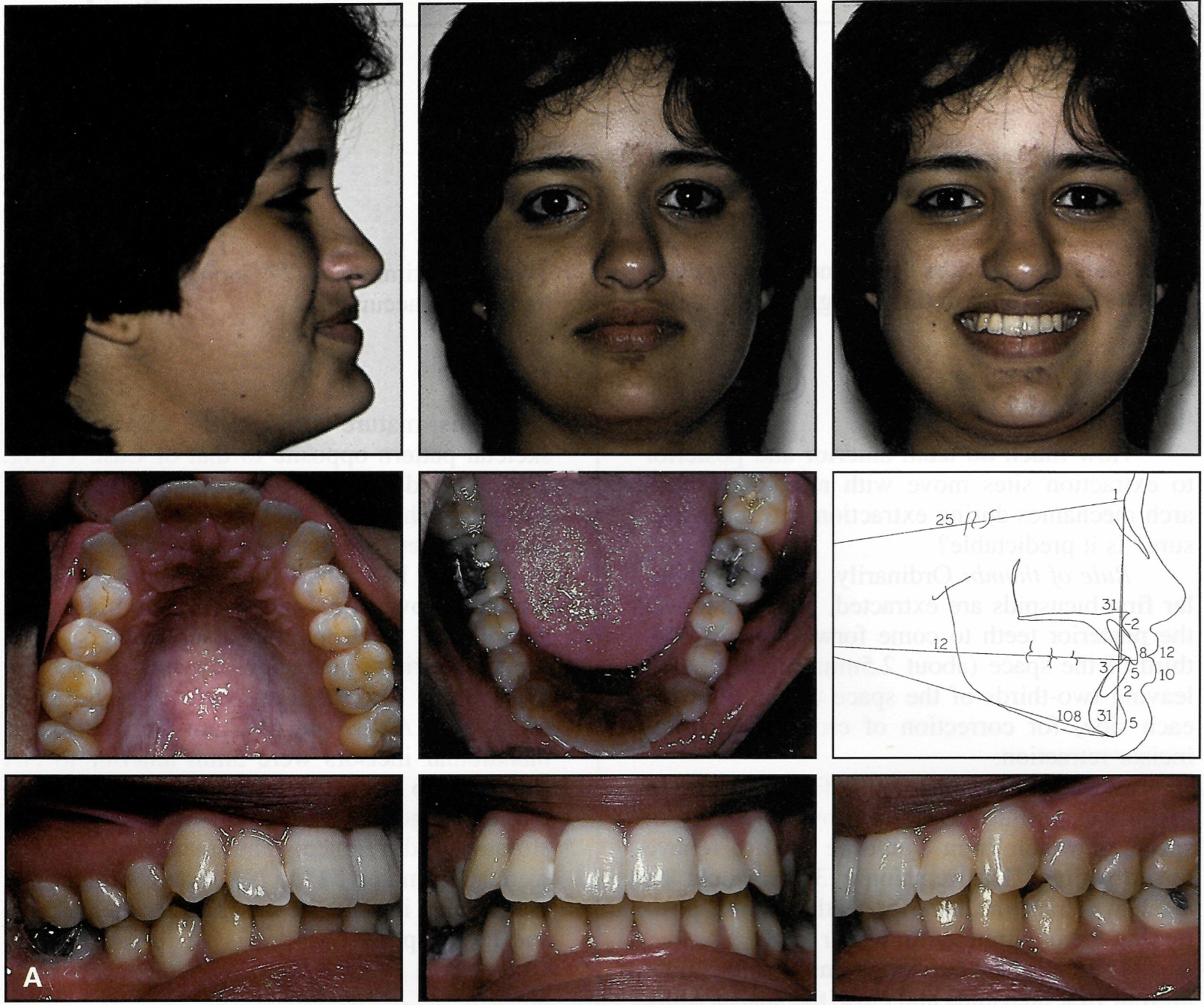
Fig. 7 A. Mature 16-year-old female with low ANB angle and half-Class II malocclusion before treatment (continued in next image).
Treatment Planning
Most orthodontists would treat this patient without extractions because of her facial features and the position of the mandibular incisors. However, I knew that with no growth and my mechanics, her maxillary teeth would become more protrusive and produce a poor result. If the goal were to position the maxillary incisors at 5mm to NA--a 3mm retraction--the mandibular incisors would have to be retracted about 2mm to reach that goal.
Rule of thumb: Ordinarily, when mandibular second bicuspids are extracted, you can expect the posterior teeth to come forward about half the extraction space. This nets about 7.5mm for correction of the crowding and retraction of the anterior teeth.
The anchorage afforded by maxillary posterior teeth is less than that of mandibular posterior teeth. Maxillary molar anchorage with first bicuspid extractions is about equal to that afforded by mandibular second bicuspid extractions. With reciprocal space closure, the molar relationship will not change. Class IIs stay Class II.
In this case, there was 1.5mm of crowding of the mandibular anterior teeth. Reciprocal space closure would have resulted in about 3mm of incisor retraction, a little more than desired. Instead of using extraoral anchorage to correct the overjet, Class II elastics could be used to bring the mandibular posterior teeth forward 1mm or so and thus reach the goal.
The treatment plan was to extract the maxillary first and mandibular second bicuspids and to correct the overjet with Class II elastics. An .018" X .025" Mobil-Lok‡‡ self-locking appliance was used on the maxillary arch and the mandibular molars. Uni-Twin brackets were used on the rest of the mandibular teeth. The maxillary anterior brackets were later replaced due to breakage.
Results
An excellent occlusion was achieved, with a beautiful smile in a beautiful face (Fig. 7B). The patient finished with a -2mm convexity and a 1º ANB. A and B points were each recontoured 1mm with the retraction of the incisors. The maxillary incisors finished at 5mm and 26º to NA, with a 6º torque to the archwire plane. The mandibular incisors finished at 1mm to NA, 0mm to APo, and 4mm and 27º to NB, with a 4º torque to the archwire plane. Pogonion was at 6mm to NB, with a -2mm Holdaway difference. Treatment time was 21 months.
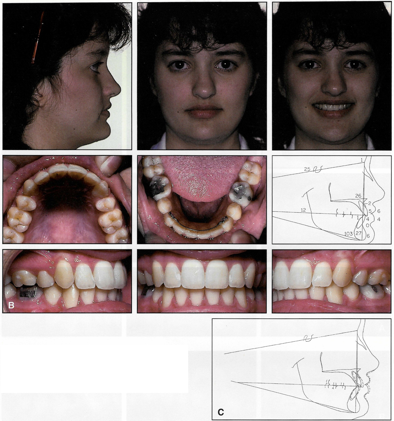
Fig. 7 (cont.) B. After 21 months of treatment and four months of retention. C. Superimposition of before-and-after cephalometric tracings.
Notice that the mandibular incisor and pogonion were both at 5mm to NB at the beginning of treatment, but at 4mm and 6mm, respectively, at the end of treatment. Without a superimposition, the data indicate that the mandibular incisors were retracted 1mm and pogonion grew 1mm. In fact, that is not what happened. The incisors were retracted 2mm, B point was recontoured 1mm lingually, and pogonion didn't change (Fig. 7C).
Flattening of the mandibular plane angle, especially in low-angle cases like this one, can also lead to a misinterpretation of the raw data concerning incisor movement on the mandible and the growth of pogonion. Rotation of the mandible rotates the mandibular incisor lingually and pogonion labially relative to NB, changing the Holdaway difference without an actual movement of the incisor on the mandible. This contributes to the facial features observed in low-angle skeletal patterns (see Case 5).
Case 3
A 21-year-old female presented with a partial Class III occlusion on the left side, a Class I molar relationship on the right side, the maxillary left lateral incisor in crossbite, and the maxillary and mandibular midlines shifted to the right (Fig. 8A). The maxillary right lateral incisor was severely rotated and in crossbite. The maxillary right canine had been extracted many years before. Both mandibular canines were blocked out of the arch, and the mandibular right lateral incisor overlapped the first bicuspid. There was 15mm of crowding in the mandibular arch. The maxillary and mandibular incisors were upright, with inclinations of 6º and -18º, respectively.
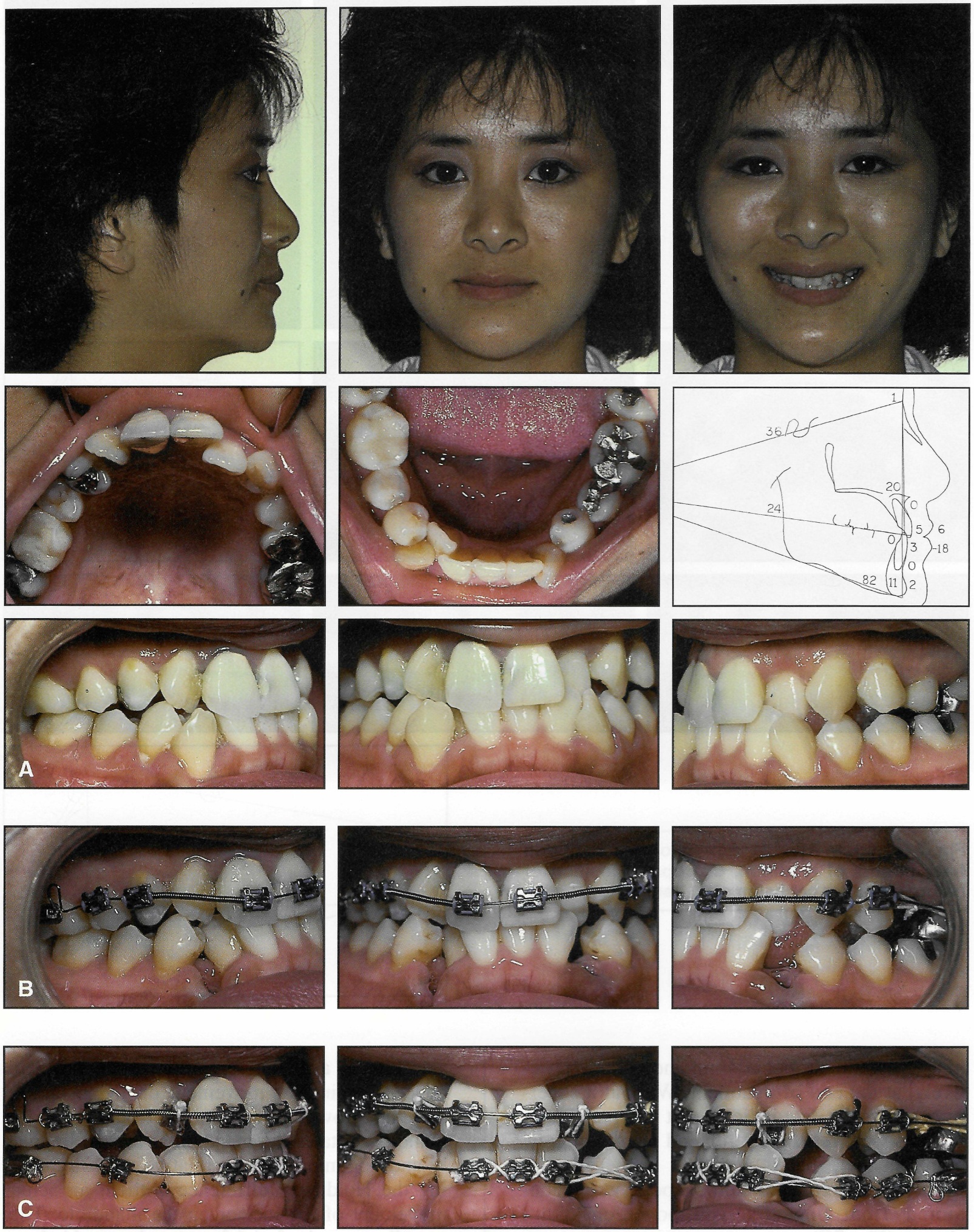
Fig. 8 A. 21-year-old female with severely crowded Class Ill malocclusion before treatment. B. Initial .016" stainless steel archwire with stops set, coil springs to open spaces for lateral incisors, and elastic thread to retract left premolar (just after extraction of mandibular canines). C. Maxillary lateral incisor brackets bonded upside down for 3° labial root torque; initial .016" stainless steel mandibular archwire with stops set (continued in next image).
Treatment Planning
Cephalometrically, the teeth, jaws, and soft tissue were ideal, so the goal was to keep them there. Extraction of the mandibular first bicuspids, which would yield a rule-of-thumb net 10mm of space, would require a 2.5mm forward movement of the mandibular incisors to eliminate the 15mm of mandibular crowding. Additionally, and more troublesome, the man dibular right molar would come forward 2.5mm with space closure, but the maxillary right molar would not, since the maxillary right canine was not present and space was needed to rotate the lateral incisor. If only reciprocal mechanics were used, it would create a Class III molar relationship on the right side. If the maxillary left first bicuspid were extracted, a Class III molar relationship would result that could require surgery to resolve. An alternative approach would be to extract mandibular canines instead of first bicuspids.
Rule of thumb: Canine extractions net approximately 15mm. The entire extraction space can be used for incisor alignment and retraction, since the posterior teeth will not move forward at all.
With no mesial movement of the mandibular buccal segments, the Class I relationship on the right side would be preserved. The canine space on the left side would provide adequate space to correct the mandibular midline, but would not leave space for the retraction of the anterior teeth.
In the maxillary arch, the left second bicuspid could be extracted instead of the first bicuspid. This would result in the maxillary canine moving back less and the maxillary molar moving forward more into a Class I occlusal relationship, without the need for Class III elastics.
Treatment was carried out with an Andrews-prescription .018" X .025" Uni-Twin appliance (Fig. 8B). Maxillary lateral brackets with 3º of torque were bonded upside down to produce -3º of torque, which brought the roots forward without requiring torque to be bent into the archwire (Fig. 8C). Arch length was maintained with stopped archwires during alignment of the upper and lower teeth, and all remaining spaces were then closed with closing-loop archwires (Figs. 8D, 8E).
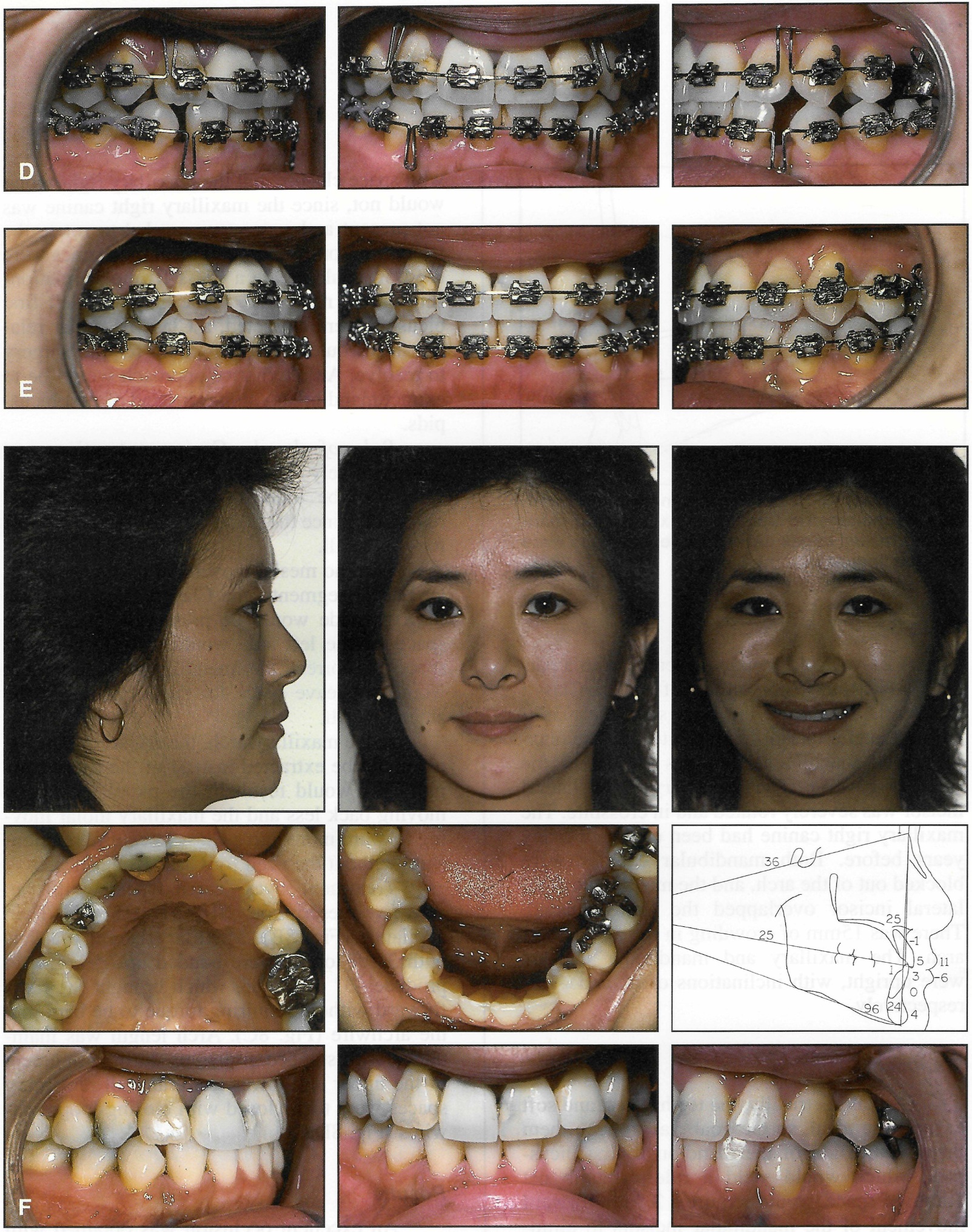
Fig. 8 (cont.) D. After alignment and rotation of all teeth, remaining spaces closed with .017" x .022" closing-loop archwires. E. Final detailing with .018" x .025" finishing wires. F. After 19 months of treatment and 10 months of retention (continued in next image).
Results
An excellent occlusion was obtained with no appreciable change in the face or the anteroposterior position of the teeth (Figs. 8F, 8G). The maxillary central incisor roots were torqued lingually to 25º to NA, with an 11º torque to the archwire plane. The maxillary lateral incisor roots were torqued labially by the -3º brackets. The mandibular incisor roots were torqued lingually to 24º to NB, with a -6º torque to the archwire plane. Treatment time was 19 months.
In the previous case, the maxillary central incisors were at 26º to NA, but with a 6º torque to the archwire plane. While the cant of the incisors was practically the same in this case, the torque requirements were different because of the cant of the occlusal or archwire plane.
The unusual decision to extract mandibular canines along with the maxillary left second bicuspid made this case quite simple and may have avoided jaw surgery.
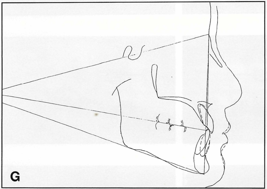
Fig. 8 (cont.) G. Superimposition of before and-after cephalometric tracings. Maxillary and mandibular incisal edges did not move, but roots were torqued lingually.
Case 4
This 13-year-old female, not yet mature, had excellent facial balance, a Class I occlusion, an average skeletal pattern, and teeth ideally positioned on the jaws (Fig. 9A). All four canines were mildly crowded out of the arch.
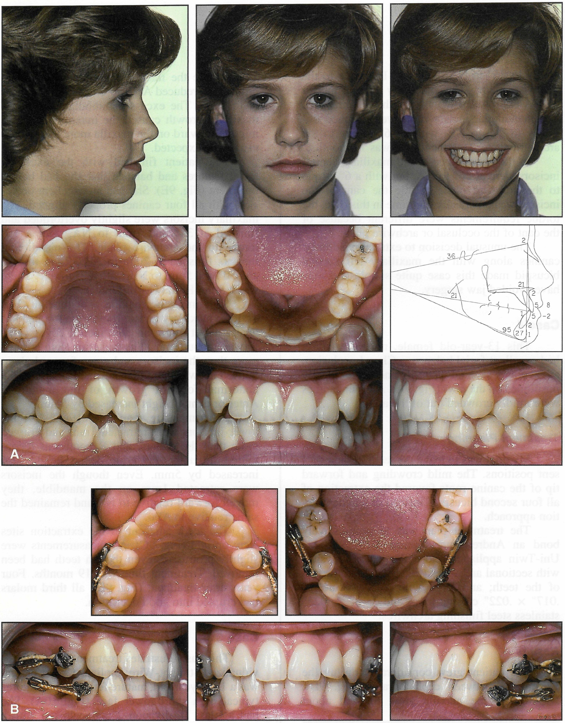
Fig. 9 A. Immature 13-year-old female with ideal Class I occlusion and skeletal pattern and mild crowding before treatment. B. After four months of treatment with sectional archwires and elastic threads; note drift of canines (continued in next image).
Treatment Planning
My goal was to leave the teeth in their present positions. The mild crowding and forward tip of the canine roots favored the extraction of all four second bicuspids instead of a nonextraction approach.
The treatment plan was to progressively bond an Andrews-prescription .018" X .025" Uni- Twin appliance; close the extraction sites with sectional archwires (Fig. 9B); bond the rest of the teeth; and align with .018" Nitinol††, .017" X .022" closing-loop, and .018" X .025" stainless steel finishing archwires.
Results
The patient grew considerably during the 22 months between cephalograms (Fig. 9D). Nasion and the maxilla grew forward about 2mm, while the mandible grew forward about 5mm. This reduced ANB to 1º and the convexity to 0mm. The excess mandibular growth vs. maxillary growth caused the maxillary teeth to migrate forward on the maxilla more than would usually be expected.
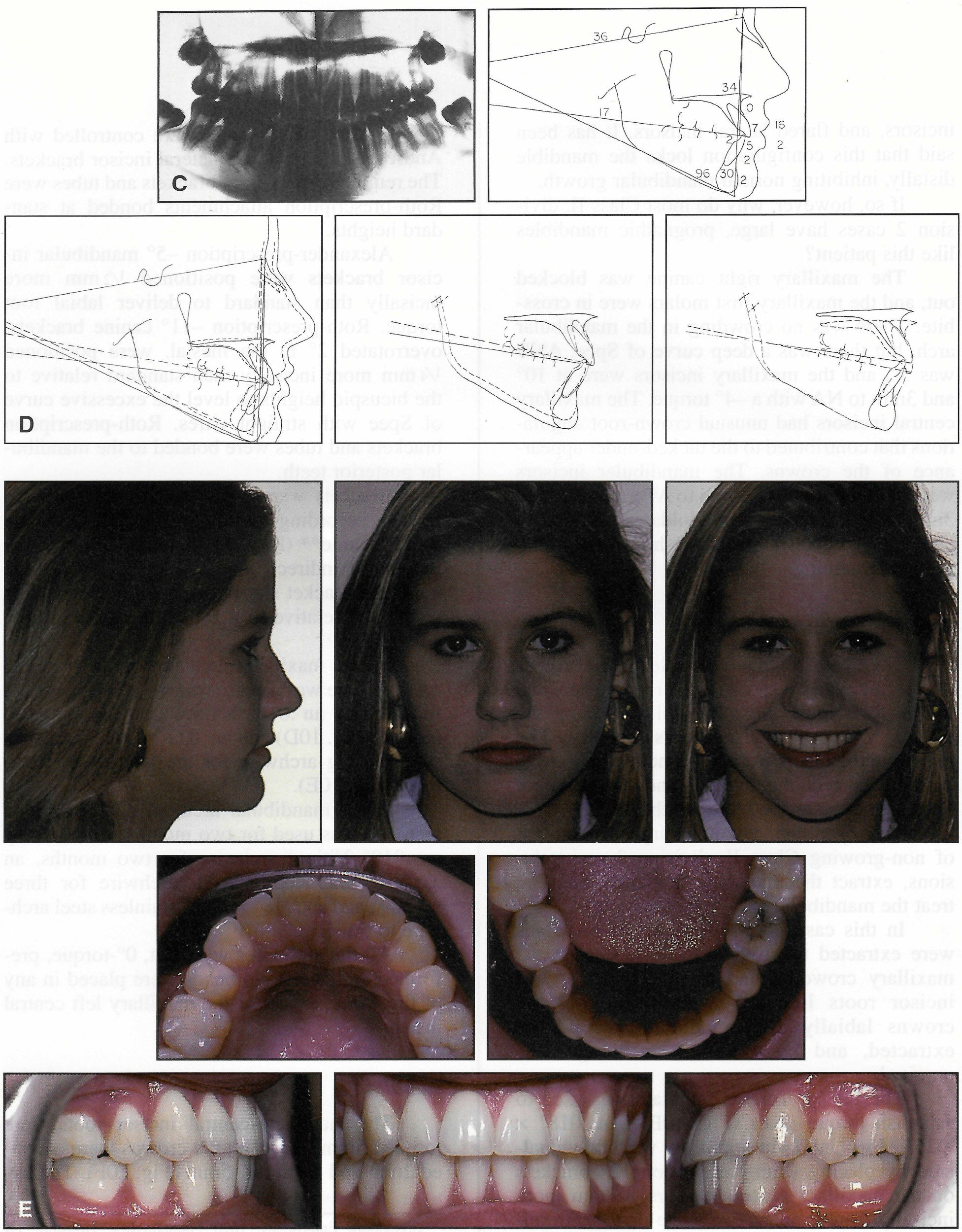
Fig. 9 (cont.) C. After 19 months of treatment. D. Superimposition of before-and-after cephalometric tracings. E. Four years after treatment.
The patient finished with the excellent facial features and balance that she had before treatment (Fig. 9E). She had an excellent occlusion with all four canines properly aligned. The maxillary incisors were slightly overtorqued and finished at 34º and 7mm to NA, with a 16º torque to the archwire plane. The mandibular incisors finished at 2mm to APo, 2mm to NA, and 30º and 5mm to NB, with a 2º torque. There was a 3mm Holdaway difference.
Superimposing maxilla over maxilla (Fig. 9D), the maxillary incisor roots were torqued lingually about 4mm, and the incisal edges came forward about 1mm. The posterior teeth erupted more than the incisors and came forward about 5mm. This was more than normal because of the abnormal forward growth of the mandible. Anterior dental height increased by 5mm.
Superimposing mandibles (Fig. 9D), the lower incisors were retracted 1mm and erupted more than the molars, and B point was recontoured lingually. Posterior dental height also increased by 5mm. Even though the incisors were retracted 1mm on the mandible, they moved forward relative to NA and remained the same relative to APo.
The teeth adjacent to the extraction sites were upright (Fig. 9C). All measurements were slightly protrusive, even though teeth had been removed. Treatment time was 19 months. Four years after treatment (Fig. 9E), all third molars had erupted into good occlusion.
Case 5
This case illustrates treatment with an individualized Straight-Wire Appliance.10 The patient was a 13-1/2-year-old, mature female with features typical of a short lower face (Fig. 10A). She had a Class II, division 2 malocclusion with a deep overbite, tucked-under maxillary central incisors, and flared lateral incisors. It has been said that this configuration locks the mandible distally, inhibiting normal mandibular growth.
If so, however, why do most Class II, division 2 cases have large, prognathic mandibles like this patient?
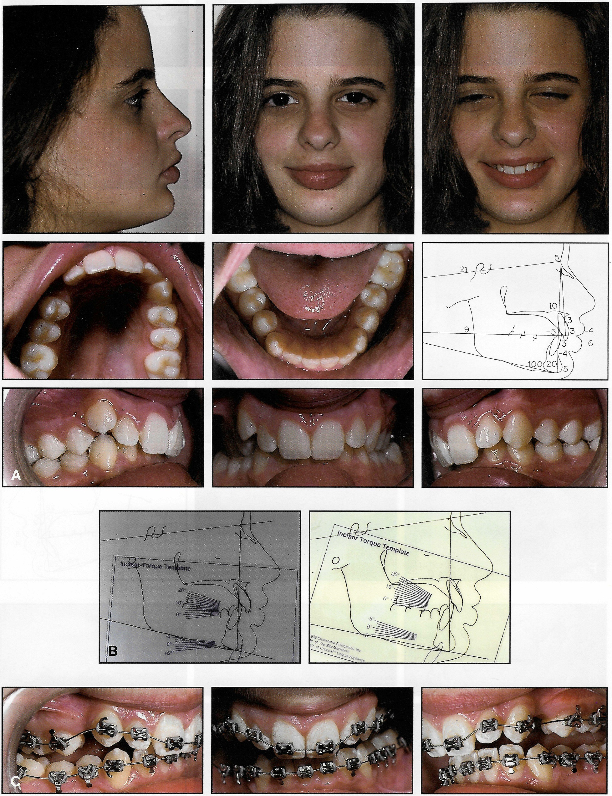
Fig. 10 A. Mature 131/2-year-old female with short lower face, Class II, division 2 malocclusion, and deep bite before treatment. B. Use of Incisor Torque Template to determine goals for torque of maxillary central incisors. C. Initial .0155" braided archwire (continued in next image).
The maxillary right canine was blocked out, and the maxillary first molars were in crossbite. There was no crowding in the mandibular arch, but there was a deep curve of Spee. ANB was 5º, and the maxillary incisors were at 10º and 3mm to NA with a -4º torque. The maxillary central incisors had unusual crown-root angulations that contributed to the tucked-under appearance of the crowns. The mandibular incisors were at -5mm to NA, -4mm to APo, and 20º and 3mm to NB, with a -2mm Holdaway difference and a 6º torque. The patient had little or no growth remaining.
Treatment Planning
The treatment plan was to leave the crowns of the maxillary central incisors in place and torque their roots lingually while torquing the maxillary lateral incisor roots labially. The mandibular incisors were to be moved forward to partially correct the overjet, and the curve of Spee was to be leveled to open the bite.
Rule of thumb: For non-surgical treatment of non-growing Class II, division 2 malocclusions, extract the maxillary first bicuspids and treat the mandibular arch nonextraction.
In this case, the maxillary first bicuspids were extracted to provide space to correct the maxillary crowding and to torque the central incisor roots lingually without moving the crowns labially. No mandibular teeth were extracted, and no extraoral anchorage was required.
The Incisor Torque Template was used to establish torque goals (Fig. 10B). An .018" X .025" Mini Uni-Twin appliance was individualized by placing Roth-prescription 12º brackets on the maxillary central incisors, ¼mm more incisally than standard to elevate these teeth relative to the lateral incisors and canines. The maxillary lateral incisor roots were controlled with Andrews-prescription 3º lateral incisor brackets. The remaining maxillary brackets and tubes were Roth-prescription attachments bonded at standard heights.
Alexander-prescription -5º mandibular incisor brackets were positioned 1/2mm more incisally than standard to deliver labial root torque. Roth-prescription -11º canine brackets, overrotated 2º to the mesial, were positioned ¼mm more incisally than standard relative to the bicuspid heights to level the excessive curve of Spee with straight wires. Roth-prescription brackets and tubes were bonded to the mandibular posterior teeth.
Brackets were positioned on the patient's models according to this prescription with the Slot Machine** (Fig. 11), then transferred to the mouth for indirect bonding. The Slot Machine holds the bracket slot in place while the tooth is positioned relative to it for tip, torque, rotation, and height.10
In the maxillary arch, an .0155" braided training wire was used for one month (Fig. 10C), followed by an .018" Nitinol archwire for three months (Fig. 10D) and an .017" X .022" stainless steel closing archwire for the balance of treatment (Fig. 10E).
In the mandibular arch, an .0155" braided archwire was used for two months, followed by an .018" Nitinol archwire for two months, an .017" X .025" Nitinol XL archwire for three months, and an .018" X .022" stainless steel archwire to finish.
All the archwires were flat, 0º-torque, preformed archwires. No bends were placed in any of the wires, except at the maxillary left central incisor.
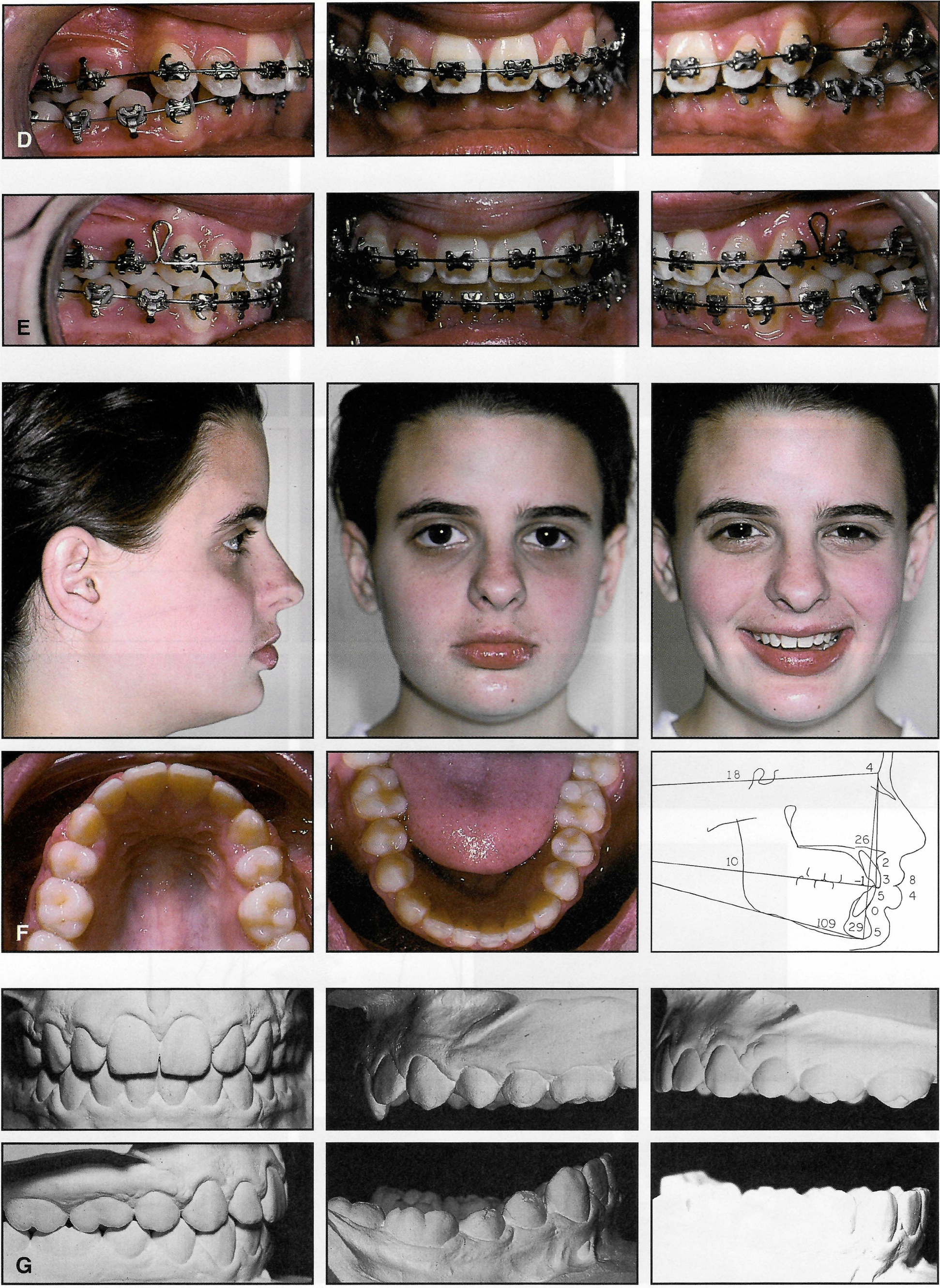
Fig. 10 (cont.) D . . 018" Nitinol archwires. E. Maxillary arch: .017" x .022" stainless steel closing archwire; mandibular arch: .018" x .022" stainless steel finishing archwire. F. After 21 months of treatment with continuous, flat archwires. G. Complete leveling of curve of Spee (continued in next image).
Results
The maxillary central incisor roots were torqued 5mm lingually; the crowns were elevated 2mm and retracted .5mm (Fig. 10F). The lateral incisor roots were torqued in harmony with the central incisors and canines.
The mandibular curve of Spee was completely leveled (Fig. 10G), but not as is purported to occur with continuous arch mechanics. Leveling with continuous arches is supposed to open the bite, increasing lower face height by elevating the molars without depressing the incisors. Utility arches are supposed to open the bite by depressing the incisors without increasing lower face height. In my opinion, there is little difference between the two approaches. In growing patients, the lower face height generally increases more or less, depending on facial type; non-growing patients experience little or no increase in lower face height, regardless of facial type.
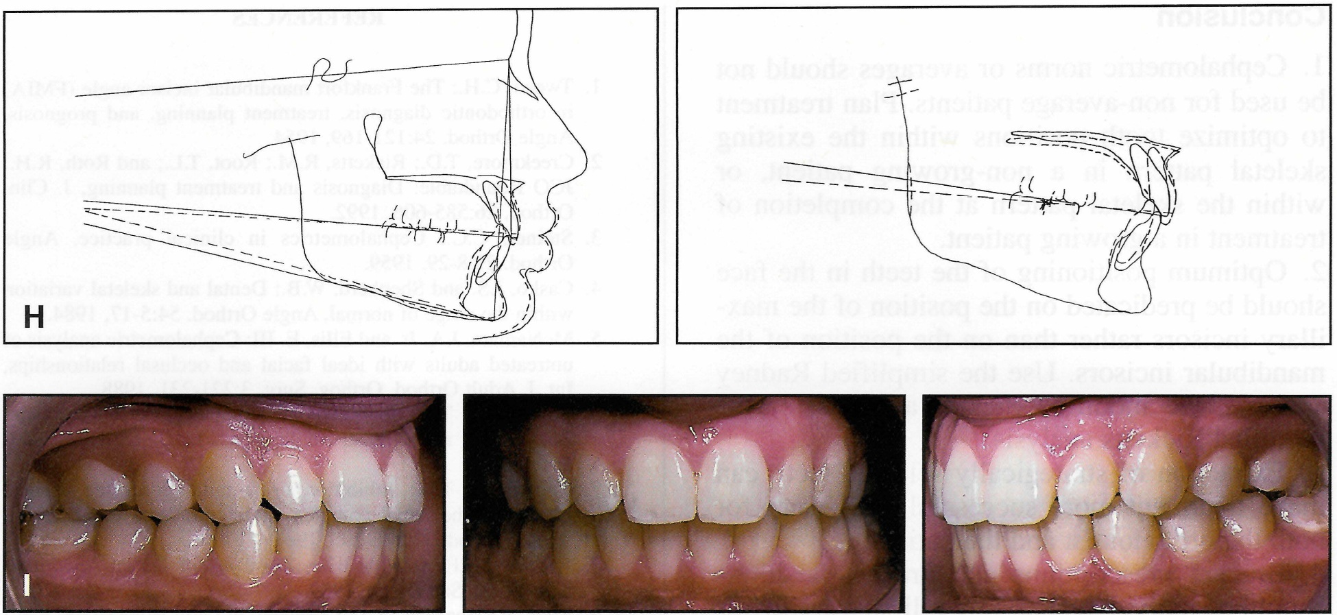
Fig. 10 (cont.) H. Superimposition of before-and-after cephalometric tracings. I. Two years after treatment.
In this case, with continuous arches, the mandibular incisors were depressed 3mm and tipped forward 2mm, finishing at 0mm to APo, with a 0mm Holdaway difference (Fig. 10H). They were at 29º and 5mm to NB, with a 4º torque to the archwire plane. Treatment time was 21 months.
There was little change in the drape of the soft tissues and, unfortunately, only a 1mm increase in lower face height. The maxillary central incisors were overcorrected to the level of the lateral incisors, and they rebounded to a normal height (Fig. 10F, Fig. 10I).
The advantages of an individualized appliance should be obvious. It is almost as easy to plan and fabricate an individualized appliance as it is to fabricate a standard appliance. So why not?
Conclusion
- Cephalometric norms or averages should not be used for non-average patients. Plan treatment to optimize tooth positions within the existing skeletal pattern in a non-growing patient, or within the skeletal pattern at the completion of treatment in a growing patient.
- Optimum positioning of the teeth in the face should be predicated on the position of the maxillary incisors rather than on the position of the mandibular incisors. Use the simplified Radney analysis, the modified Steiner analysis, or the modified Ricketts analysis.
- Extraction of strategically selected teeth can make treatment more successful and easier for both the orthodontist and the patient.
- Bracket prescriptions and bracket positions should be individualized. Use full-size archwires to minimize wire-bending and treatment time, and to achieve more predictable results. One preadjusted appliance prescription will not produce the same finished results in different malocclusions.
FOOTNOTES
- *Registered trademark of "A" Company Orthodontics, 9900 Old Grove Road, San Diego, CA 92131.
- **Creekmore Enterprises, 1620 Fountainview, Houston, TX 77057.
- ***Registered trademark of Dentaurum, Inc., 10 Pheasant Run, Newtown, PA 18940.
- †American Orthodontics, 1714 Cambridge Ave., Sheboygan, WI 53082.
- ‡Ormco, 1717 W. Collins Ave., Orange, CA 92667.
- ††Trademark of 3M Unitek, 2724 S. Peck Road, Monrovia, CA 91016.
- ‡‡l:Forestadent USA, 10240 Bach Blvd., St. Louis, MO 63132.
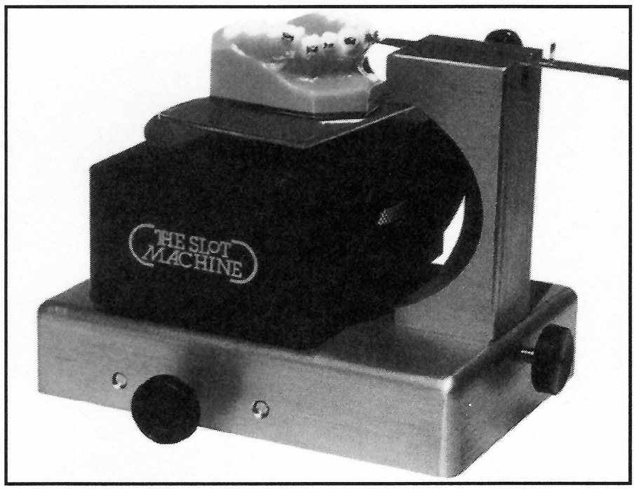
Fig. 11 Slot Machine for bracket positioning.
REFERENCES
- 1. Tweed, C.H.: The Frankfort mandibular incisor angle (FMIA) in orthodontic diagnosis, treatment planning, and prognosis, Angle Orthod. 24:121-169, 1954.
- 2. Creekmore, T.D.; Ricketts, R.M.; Root, T.L.; and Roth, R.H.: JCO Roundtable: Diagnosis and treatment planning, J. Clin. Orthod. 26:585-606, 1992.
- 3. Steiner, C.C.: Cephalometrics in clinical practice, Angle Orthod. 29:8-29, 1959.
- 4. Casko, J.S. and Shepherd, W.B.: Dental and skeletal variation within the range of normal, Angle Orthod. 54:5-17, 1984.
- 5. McNamara, J.A. Jr. and Ellis, E. III: Cephalometric analysis of untreated adults with ideal facial and occlusal relationships, Int. J. Adult Orthod. Orthog. Surg. 3:221-231, 1988.
- 6. Solow, B.: The dentoalveolar compensatory mechanism: Background and clinical implications, Br. J. Orthod. 7: 145-161. 1980.
- 7. Creekmore, T.D.: Inhibition or stimulation of the vertical growth of the facial complex: Its significance to treatment, Angle Orthod. 37:285-297, 1967.
- 8. Andrews, L.F.: Straight Wire: The Concept and the Appliance, L.A. Wells, San Diego, 1989.
- 9. Ross, V.; Isaacson, R.J.; Germane, N.; and Rubenstein, L.K.: Influence of vertical growth pattern on faciolingual inclinations and treatment mechanics, Am. J. Orthod. 98:422-429, 1990.
- 10. Creekmore, T.D. and Kunik, R.I. : Straight wire: The next generation, Am. J. Orthod. 104:8-20, 1993.
- 11. Radney, L.J.: Personal communication, 1996.
-
 DR. CREEKMORE
Dr. Creekmore is a Contributing Editor of the Journal of Clinical Orthodontics and in the private practice of orthodontics at 1620 Fountainview, Houston, TX 77057.