Simultaneous Cuspid and Bicuspid Retraction
During the discussions on cuspid retraction, bicuspid retraction, and molar protraction, it was seen that location of the bend in the extraction site determined the anchorage side. It was also emphasized that as the interbracket distances become smaller, the bend in effect becomes located closer to center, even if placed immediately against either bracket (tube) adjacent to the extraction site. The closer the bend is to the center, the lesser the differential torque. If the bend is placed in the center, the moments are equal and opposite. So, the more critical the anchorage, the more distant the bend should be from center. Even temporarily avoiding banding of the second bicuspids, during cuspid retraction, was discussed and demonstrated.
The case in Figure 126 presented in my practice following removal of the upper first bicuspids only.
Similar articles from the archive:

Fig. 126 Case presented with upper first bicuspids extracted.
She had a Class II malocclusion with lower anterior crowding. I had the lower second bicuspids removed and planned on maximizing lower intraoral anchorage until sufficient space was gained following cuspid and bicuspid retraction, at which time I would align the lower anteriors. In the upper arch, there were no anchorage problems, so the plan was to retract the cuspids only enough to break the contacts between the anterior teeth for alignment and space closure in the extraction site.
A minimal appliance was placed (Fig. 127), involving only the first molars, bicuspids, and cuspids.
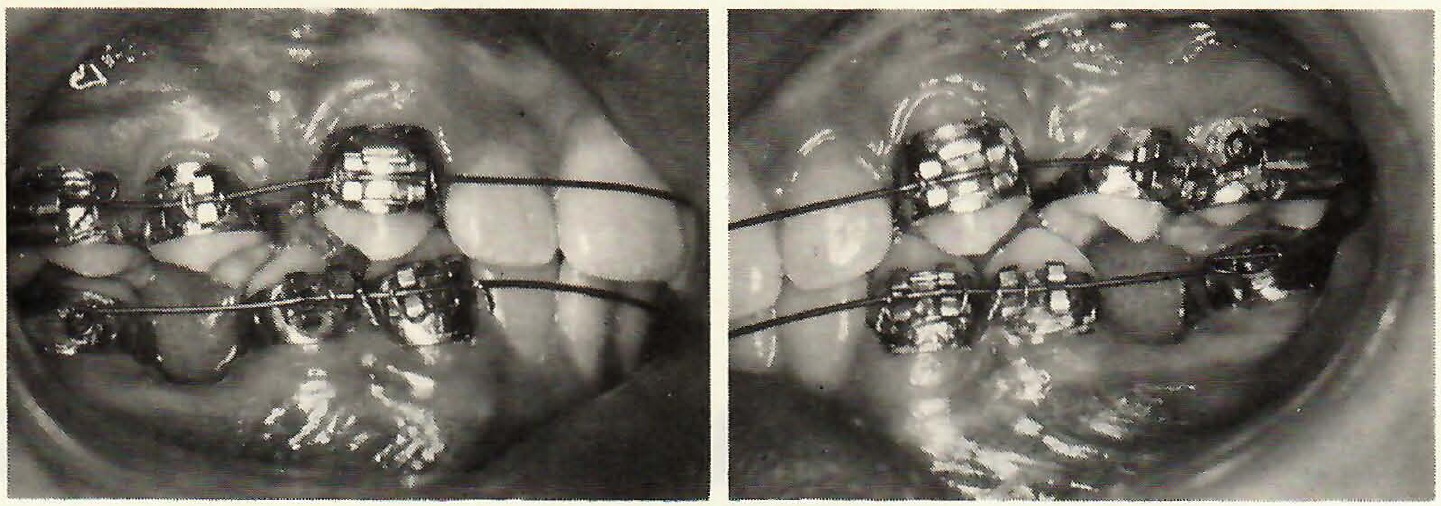
Fig. 127 Minimal appliance placed.
An .016 archwire was placed, and it can be seen that wire/bracket engagement resulted in activation due to the malocclusion itself. This automatically produces the initial periodontal response for tooth movement. It can also be seen that the bracket ties were not placed next to the extraction sites on the lower first bicuspids, as rotation during space closure was desired.
Figure 128 shows placement of the bends intraorally.
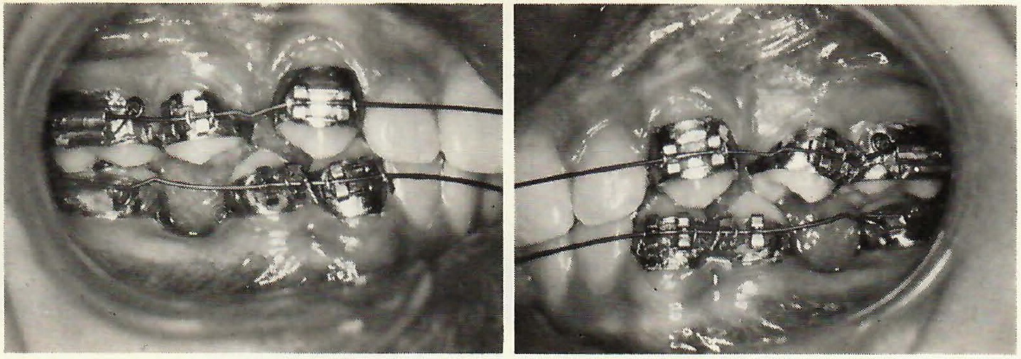
Fig. 128 Placement of intraoral bends in archwire.
Note in the upper arch that the bends were placed in the center, because this produces equal and opposite moments with no effective anchorage. Some deformation can be seen. This deformation will tend to occur if the archwire bends are placed prior to attaining reasonable bracket alignment. When this does occur, the Tweed loop pliers can be placed over such bend at the following visit, and the bend reactivated.
In the lower arch, notice that the bends are located toward the molar tubes, indicating that this is the anchor side of the extraction site. If desired, the bend can be placed in the archwire outside of the mouth, thereby permitting closer placement to the molar tubes and thus a greater distance from the center of the wire lying across the extraction sites. You might notice and wonder why the 360° tieback loops are bent in the direction shown, since good spring design calls for a wire to continue bending in the same direction as formed, when it is activated by wire/bracket engagement. The answer simply is that this is not the ideal design. But it is easy, practical, and works. It can be any loop you wish, made in any manner you choose.
The occlusal views (Fig. 129) show the minimal strap-up in this case.
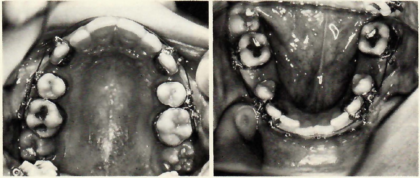
Fig. 129 Occlusal views of minimal appliance placed.
I would like to again emphasize the importance of putting in toe-in bends at this point to create a counterrotation for space closure, as the terminal teeth (molars) will attempt to undergo a mesiolingual rotation. For a long time, I was guilty of this error, and I can assure you it is a lot nicer not to produce an undesirable molar rotation than it is to correct one with the archwire only, especially since I use no lingual attachments and therefore no lingual elastics. If you use lingual elastics, you are not faced with the same problem. I used to place my toe-in bends after beginning space closure, but strongly recommend placement prior to this time. It is not necessary to worry about overrotation, as this situation can easily be corrected--simply by engaging an elastic from the molar tube to the bicuspid bracket at the end of treatment. The archwire, in such case, would be fully engaged in the bicuspid bracket and would also terminate at this point. Simply cut off the wire distal to the bracket.
In Figure 129, notice that the lower crowding occurs all the way from bicuspid to bicuspid. It probably SEEMS ridiculous to even consider the idea of retracting cuspids and bicuspids against first molars, but it will be done. This is in direct contrast to those who guard anchorage so closely, that only a single tooth is retracted at a time. Also note that the bicuspids are rotated, as any distal force applied at the bicuspid brackets will cause such teeth to rotate--in this case, desirably. Since the "Cue Ball Concept" can be applied here, it makes sense to retract the bicuspids first, thus obtaining needed space and accomplishing the rotations at the same time.
As we follow the lower progress (Fig. 130), we can see that retraction elastics are placed from the bicuspids to the first molars. I no longer use an elastic thread, but a power chain instead. Whatever provides the necessary force is fine and the choice is yours. The cue ball concept tells us that since the force (distal) is being applied at the bracket which is located off center (buccal) from the crowns, the bicuspids ("cue balls") should rotate and move in a line distally. Figure 131 shows that this occurs. Now that the bicuspids have been partially retracted and rotated, the bicuspids and cuspids will be retracted simultaneously to gain further space for the incisors. Note the crowding that existed from the start, so that we can CLINICALLY evaluate the response. In Figure 132, the elastics are attached from the molars to the cuspids.
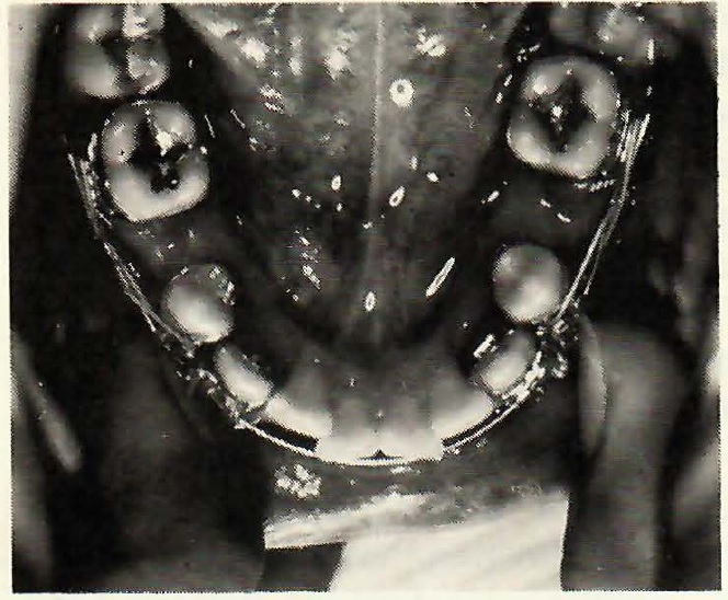
Fig. 130 Retraction elastics placed from molars to bicuspids.
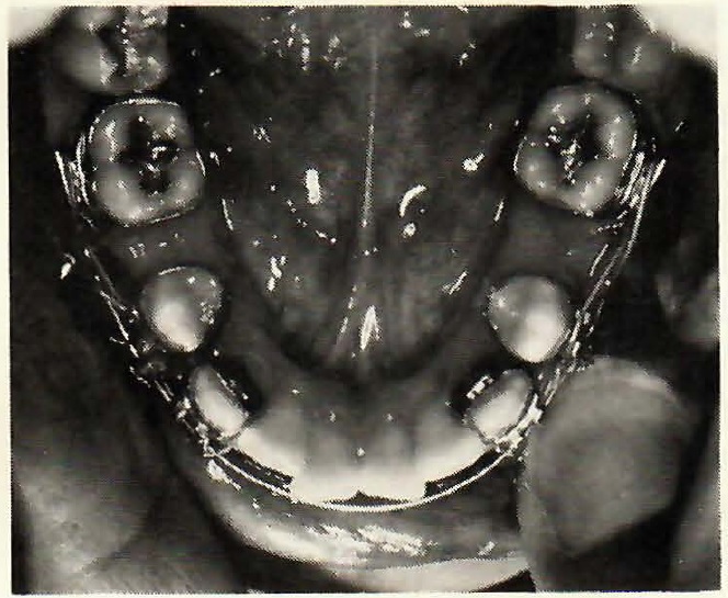
Fig. 131 Cue ball effect results in rotation of bicuspids with retraction.
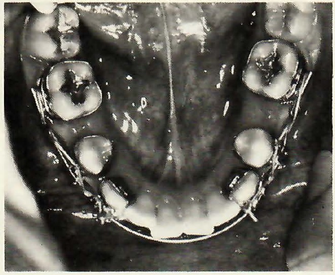
Fig. 132 Retraction elastics placed from molars to cuspids.
As the maxillary cuspids are retracted, using only a center bend, it can be observed that the contact areas are separating (Fig. 133). No attempt is made to conserve anchorage.
Observe in Figure 134 that the upper extraction spaces have been almost closed. The center bend continues to produce equal and opposite torque for root paralleling, and the space closing elastics prevent the extraction spaces from reopening. Remember, the equal and opposite moments from the archwire tend to bring roots "together" and crowns "apart". If you will look at the original malocclusion (Fig. 126), you will note basically the same molar relationship. Remember, no attempt was made to restrain maxillary molars from moving forward some. But, since we are analyzing movement by clinical observation, we must apply "common sense". The lower molars COULD be moving forward and thus be deceiving our clinical interpretation. You can see that the lower first molars are maintaining a reasonably upright condition, while the lower bicuspids and cuspids are tipping.
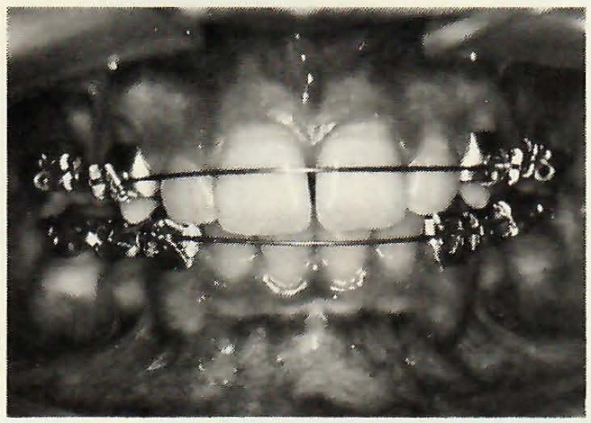
Fig. 133 Incisors space as cuspids retract.
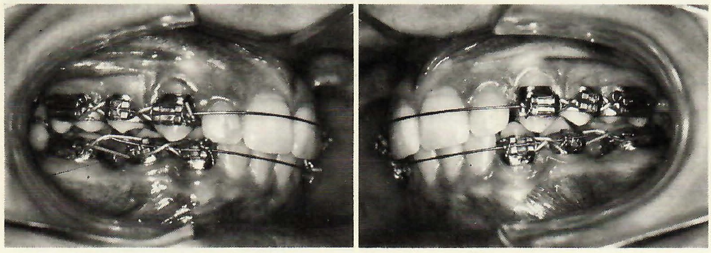
Fig. 134 Upper extraction spaces almost closed, with no apparent change in molar position.
Today, at this point, since the cuspid relationship is now Class I, I would normally bond the incisors and begin lower molar protraction. But, I decided for photographic purposes to continue retracting the bicuspids and cuspids. This means that since the upper extraction spaces are closed, further change in cusp relationships will tell us clinically what is taking place in the lower arch. We can also relate these changes to the remaining spaces and the original crowding and arrive at further supportive conclusions.
Next (Fig. 135), further retraction is observed and significant lower anterior spacing has occurred.
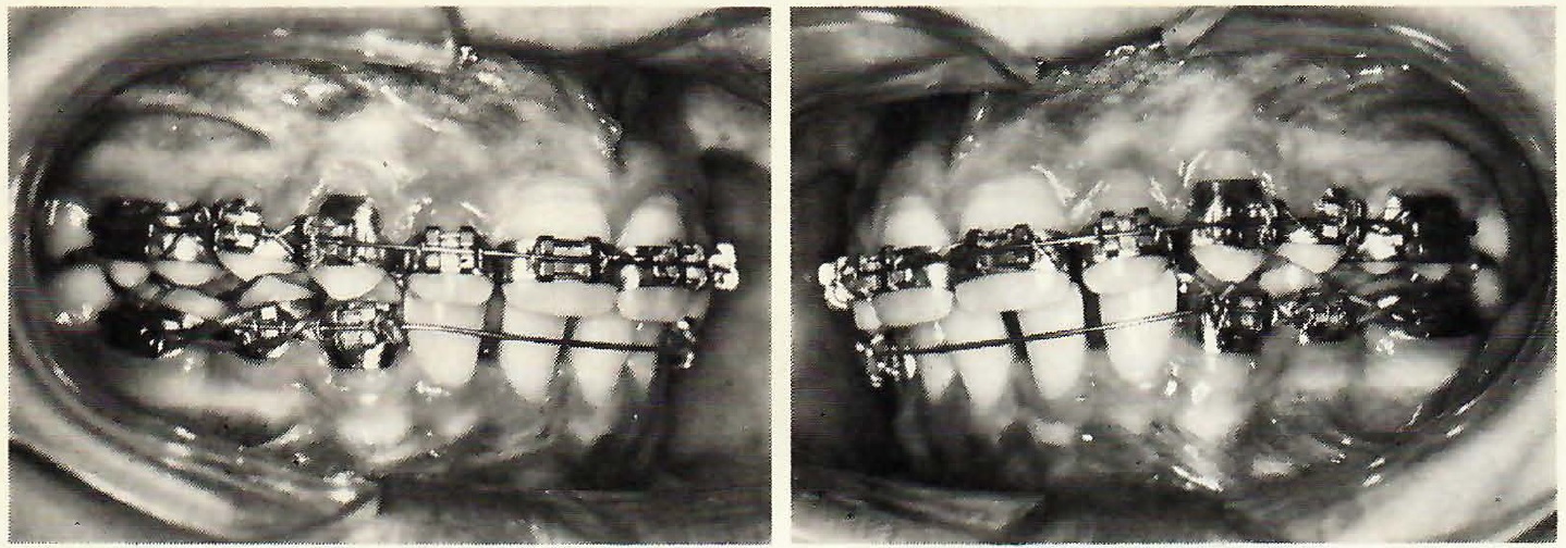
Fig. 135 Significant lower anterior spacing with further retraction.
The molar relationship remains pretty much the same, but the lower cuspids have now been retracted into a Class II relationship. When the molar starts to exhibit tipping, as seen on the lower right side, too much force is being used. The tooth should be allowed to upright before continuing further space closure.
In Figure 136 there remains significant extraction space on the patient's lower left side in spite of all the space gained in the anterior.
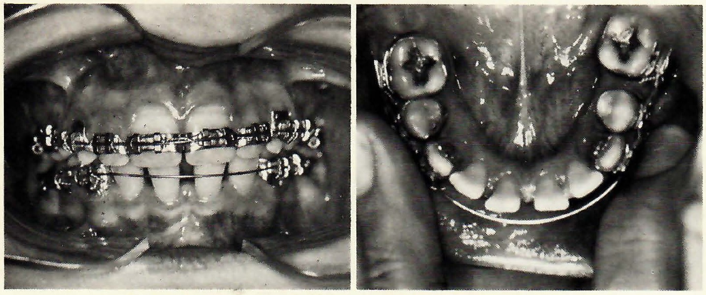
Fig. 136 Significant space both anteriorly and in the extraction site.
The lower left molar is a good example of what I mean when I say it is necessary to place an early toe-in bend for counterrotation. Lingual elastics could prevent this mesiolingual molar rotation, but I do not use lingual attachments for reasons I will later discuss. Keep in mind that we started with differential torque, and this differential is gradually diminishing as the interbracket distance continues to become smaller.
After space closure was completed, the incisors were banded and the anterior spaces closed (Fig. 137), and then the mechanics were reversed with Class II elastics.
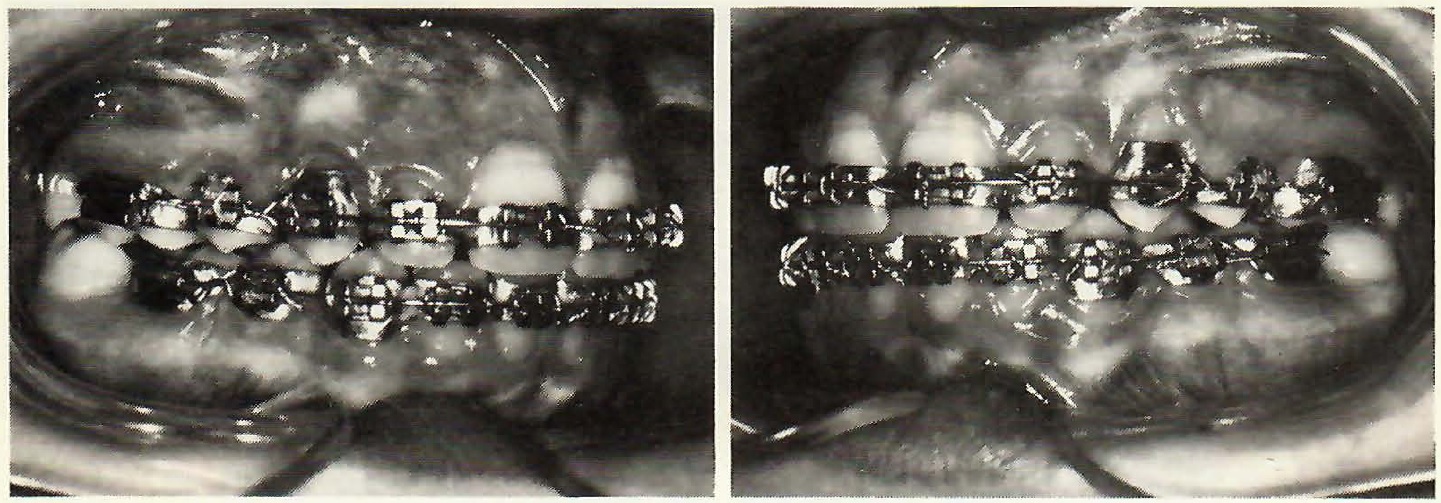
Fig. 137 Anterior spaces closed.
This was not the original plan, remember. It was first planned to protract lower molars after retracting the cuspids into a Class I relationship, and the plan was altered for photographic purposes. But, at the same time, you can see that a "cookbook" routine does not have to be followed.
The occlusal views at this stage (Fig. 138), show that toe-in bends are still being used for rotation, and for the FIRST TIME, spaces are observed distal to the lower first molars as a result of reversing mechanics with Class II elastics.
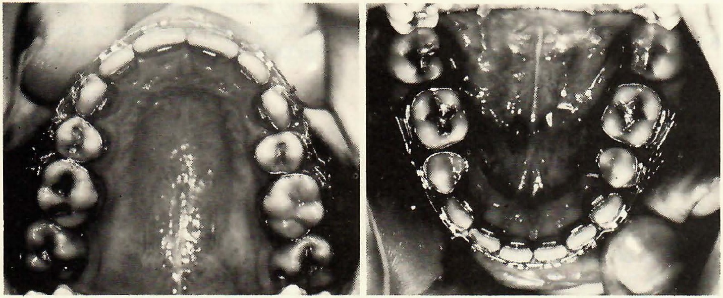
Fig. 138 Occlusal views. Toe-ins still in place for molar rotation.
Following appliance removal and during night retention (Fig. 139), the anchorage effects can still be observed.
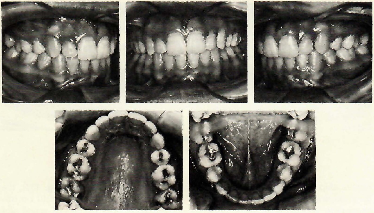
Fig. 139 Case in retention.
On completion of space closure, the anchor bend (off-center) became a center bend and resulted in equal and opposite moments producing root parallelism between first molars and first bicuspids. The lower cuspid roots, however, did not receive the "direct" effects of these moments as evidenced by their inclination. This is why I say we can be "practical" when we think of only the teeth adjacent to the extraction site, as the force system has its most direct effect here. Eventually, other teeth are affected, but I think the effect of the molar moment, here is quite obvious. Since the anterior-posterior position of the maxillary incisors remained unchanged, zero overjet before and after treatment is additional clinical evidence of the net movement in the lower arch.
Summary
I realize the word "clinical" has been used frequently. This is in no way intended to be opposed to the taking of routine progress headfilms, etc. Because there are many ways to treat cases, and many variations in interpretation of headfilms, it seems only logical to me that we should have the additional tool of "clinical judgment". Some seem to possess this attribute from birth, but it can be learned if one possesses the important tool of "common sense". There are many changes occurring each day before our very eyes as we treat our patients. Realistically, we are not going to take a progress headfilm everytime a patient comes through the door. By the time the film is developed, traced, and analyzed, the patient has usually left the office and the appliance is back at work. I think we should be capable of deciding what the appliance should do BEFORE the patient leaves the office.


