The Spider Screw for Skeletal Anchorage
Orthodontic movements such as anterior retraction and intrusion of overerupted teeth are difficult to achieve without undesirable reciprocal movements of the anchorage units.1-3 Titanium miniscrews not only provide nondental anchorage, but they are inexpensive, small, simple to place, immediately loadable, and well tolerated by patients.4-9
This article describes a new titanium miniscrew and shows several of its clinical applications.
The Spider Screw
The Spider Screw* (Fig. 1) is a self-tapping miniscrew available in three lengths--7mm, 9mm, and 11mm--in single-use, sterile packaging. The screw head has an internal .021" × .025" slot, an external slot of the same dimensions, and an .025" round vertical slot. It comes in three heights to fit soft tissues of different thicknesses: regular, with a thicker head and an intermediate-length collar; low profile, with a thinner head and a longer collar; and low profile flat, with the same thin head and a shorter collar (Fig. 2).
Similar articles from the archive:
- The Zygoma Anchorage System August 2002
- The Miniplate with Tube for Skeletal Anchorage July 2002
- Clinical Application of Micro-Implant Anchorage May 2002
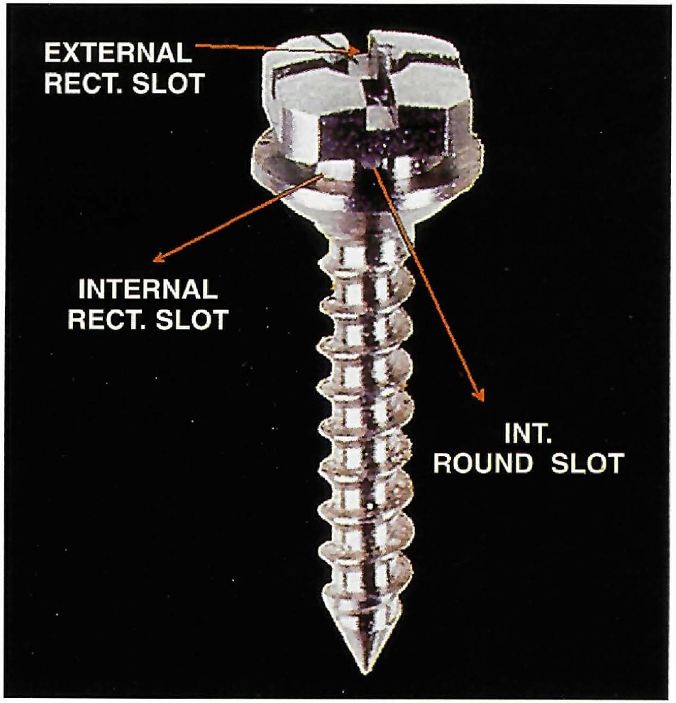
Fig. 1 Spider Screw.
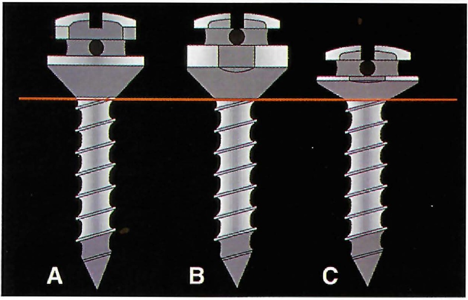
Fig. 2 Different heights of Spider Screw. A. Regular. B. Low profile. C. Low profile flat.
All three types are small enough to avoid soft-tissue irritation, but wide enough for orthodontic loading. The biocompatibility of titanium ensures patient tolerance, and the Spider Screw's smooth, self-tapping surface permits easy removal at the completion of treatment.
Surgical Procedure
The placement site should have enough bone depth to accommodate the screw length and at least 2.5-3mm of bone width to protect adjacent dental roots and anatomic structures such as the maxillary sinus or the inferior alveolar nerve. Typical insertion areas include the maxillary tuberosity, the retromolar areas, edentulous ridges, interradicular septi, the palate, and the anterior alveolar processes above the apices.
If the screw is to be placed in an area where there is a possibility of damaging adjacent structures, a surgical index should be fabricated from orthodontic wire and thermoplastic or acrylic (Fig. 3). The acrylic fits over the occlusal surfaces of the teeth near the surgical site, and the wire is inserted in the acrylic and bent so that its tip corresponds to the point of screw placement, which is marked with a pressure point or a methylene blue dot on the soft tissue. The distance from the index point to the adjacent anatomic structures can be determined radiographically using the long-cone parallel technique (Fig. 4).
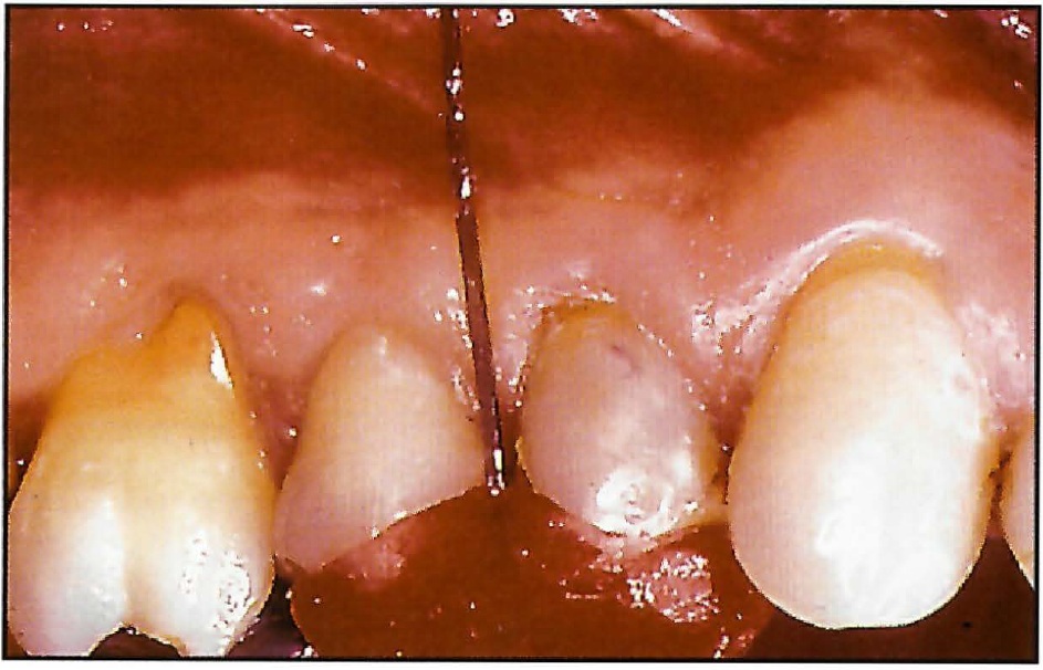
Fig. 3 Acrylic surgical index with orthodontic wire extending to point of screw insertion.
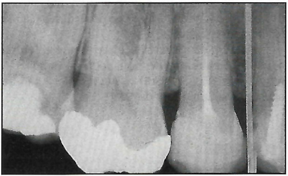
Fig. 4 Radiographic evaluation of screw placement site using surgical index.
A water-cooled 1.5mm pilot drill with a stop corresponding to the length of the Spider Screw is used to perforate the soft tissue and cortical bone (Fig. 5). A low-speed handpiece should be used--straight for anterior locations or contra-angular for buccal or posterior locations. No separate incision is required if the area has sufficient attached gingiva.
The Spider Screw is removed from its sterile package and mounted on the pick-up device of a low-speed contra-angle for insertion at about 30rpm (Fig. 6). A manual screwdriver is then used for final turning until the screw collar reaches its ideal position.
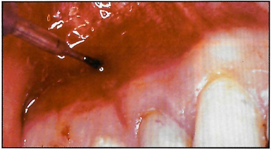
Fig. 5 Osseous site preparation with 1.5mm pilot drill.
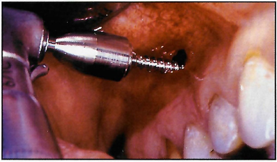
Fig. 6 Spider Screw insertion with low-speed contra-angle.
If the screw location is surrounded by mucosa, a small, 5mm vertical incision can be made and the flaps separated without removing tissue or denuding alveolar bone. In areas where the bone is extremely compact, initial placement can be facilitated by using a 1.8mm bur to drill deeper and reach less compact bone.
Once the screw has been inserted--especially in sites with poor bone quality--it must be loaded immediately to promote mechanical stability. Because miniscrews rely on mechanical retention rather than osseointegration for their anchorage, the orthodontic force should be perpendicular to the direction of screw placement. Applied forces can range from 50g to 200g, depending on the quality of the bone and the orthodontic movement desired.3 If any mobility is noted immediately after placement or during tooth movement, the screw should be inserted deeper into the bone, or replaced with a longer screw to engage the opposite plate of cortical bone.
Oral hygiene is simplified by the low profile of the screw head. For the first seven days, the patient should rinse with a .12% chlorhexadine solution. Normal hygiene procedures can be followed thereafter.
The Spider Screw is easily removed with a manual screwdriver, without local anesthetic in most cases (Fig. 7). Soft-tissue recovery can be expected within a few days.
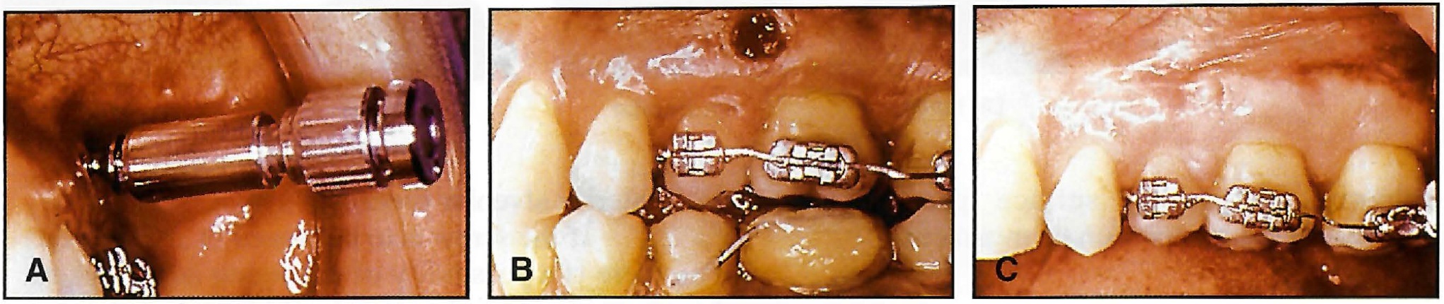
Fig. 7 A. Spider Screw removal. B. Immediately after removal. C. Seven days later.
Case 1
A 50-year-old female presented with overeruption of the upper left second premolar and first and second molars due to missing antagonists in the lower left quadrant (Fig. 8). The extruded teeth made the patient's smile unesthetic and precluded the restoration of the lower left edentulous area with osseointegrated implants.
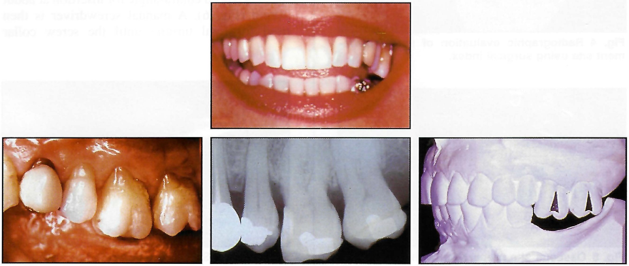
Fig. 8 Case 1. 50-year-old female with overerupted maxillary posterior teeth before treatment.
Anchorage for orthodontic intrusion of the upper left posterior teeth was provided by two Spider Screws: one in the interradicular septum between the upper left first and second premolars, and the other distal to the upper left second molar. Brackets were bonded to the extruded molars, and an .016" × .022" sectional archwire was used to consolidate the teeth. Two Sentalloy** coil springs exerting 100g each of intrusive force were attached between the Spider Screws and the brackets.
Professional scaling and gentle root planing were performed periodically to supplement the patient's oral hygiene.10 After eight months of treatment, a bracket was bonded to the upper left second premolar, and an elastic was attached from the mesial Spider Screw (Fig. 9). The maxillary curve of Spee was leveled in another two months (Fig. 10).
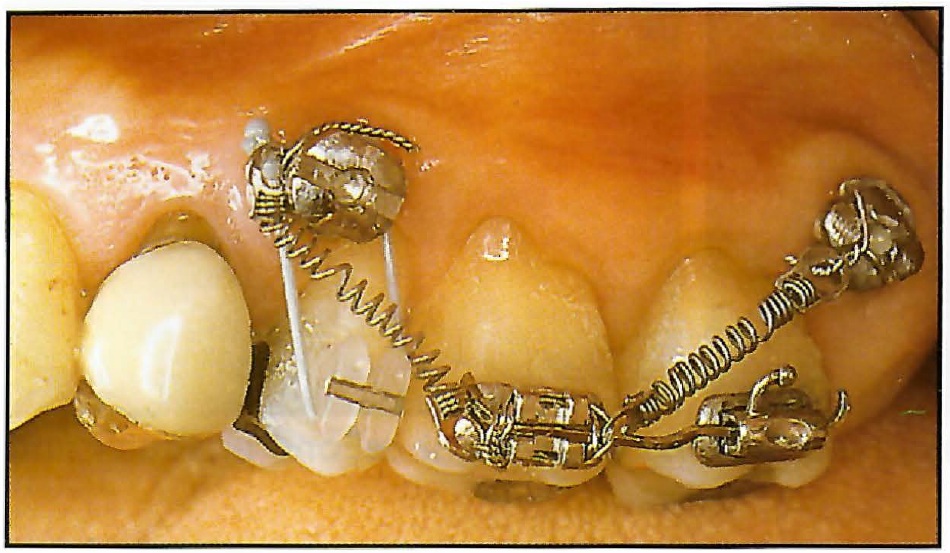
Fig. 9 Case 1. Intrusion of left second premolar and first and second molars using coils springs and elastic to Spider Screws.
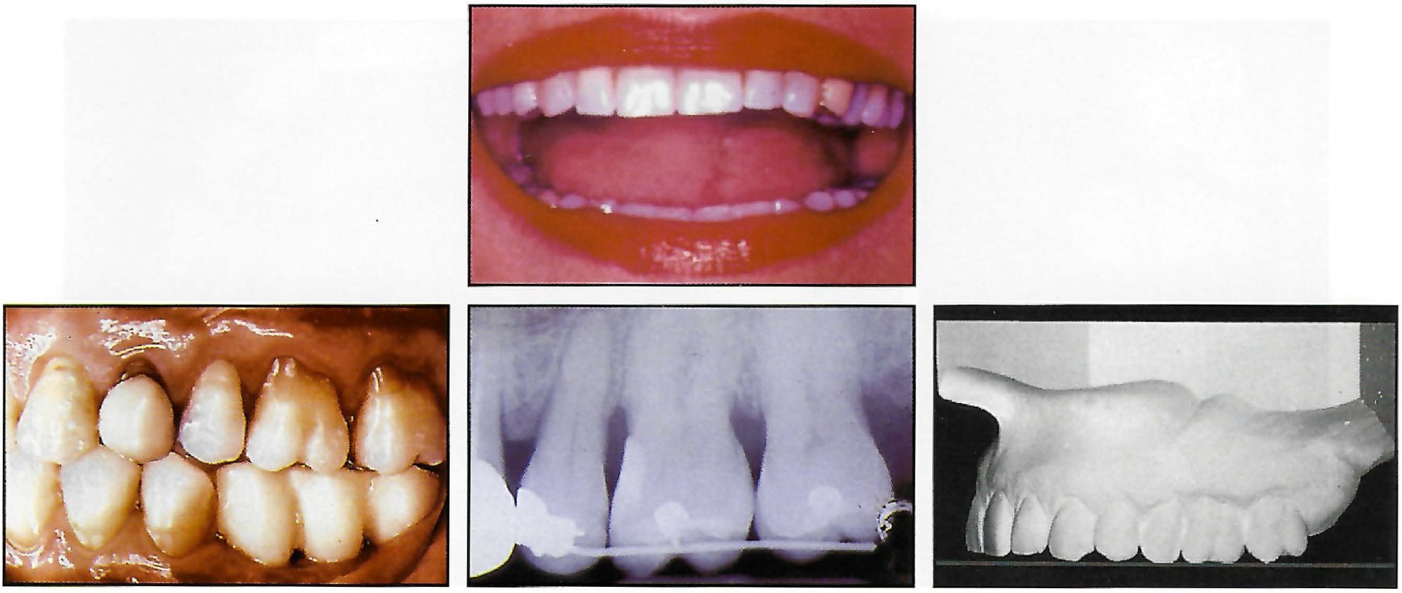
Fig. 10 Case 1. Patient after 10 months of treatment.
Case 2
A 58-year-old female presented with a Class II malocclusion; the upper right second premolar and first molar were missing, and there was a temporary bridge from the right first premolar to the second molar (Fig. 11). The upper right lateral incisor was rotated and had a carious lesion on the mesial side.
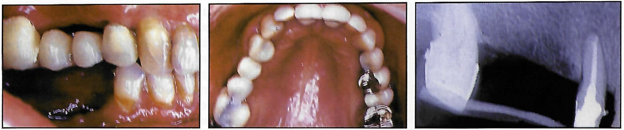
Fig. 11 Case 2. 58-year-old female with Class II malocclusion and missing upper right second premolar and first molar before treatment.
Adequate anchorage to retract the upper right first premolar and canine with a segmented approach could not be provided by the second molar alone. Therefore, the bridge was removed, and a Spider Screw was inserted into the edentulous ridge at the level of the second premolar (Fig. 12).
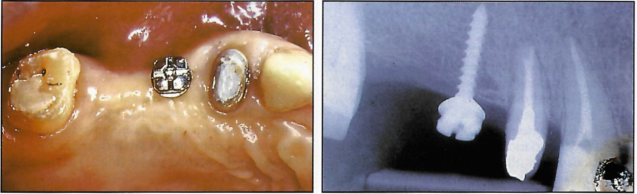
Fig. 12 Case 2. Insertion of Spider Screw.
The miniscrew served as the mesial abutment for a new temporary bridge (Fig. 13).
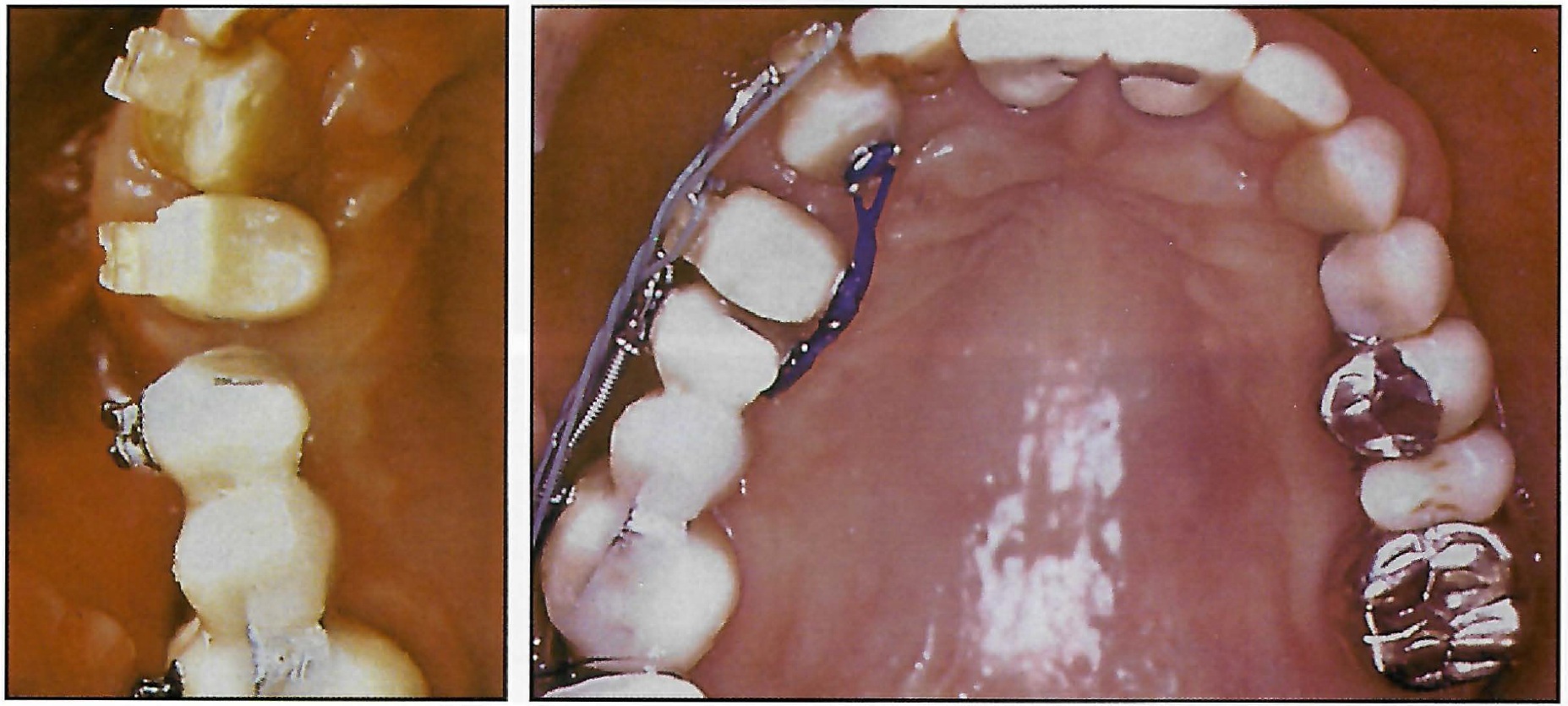
Fig. 13 Case 2. New temporary bridge anchored to Spider Screw during canine retraction.
Brackets were bonded in the maxillary arch, and an .016" × .022" segmental archwire was placed. The upper right first premolar and canine were retracted with 150g elastic forces applied to their buccal and lingual surfaces (Fig. 14). The upper right lateral incisor was rotated into proper alignment. The Spider Screw was then removed, and a final prosthetic restoration was made.
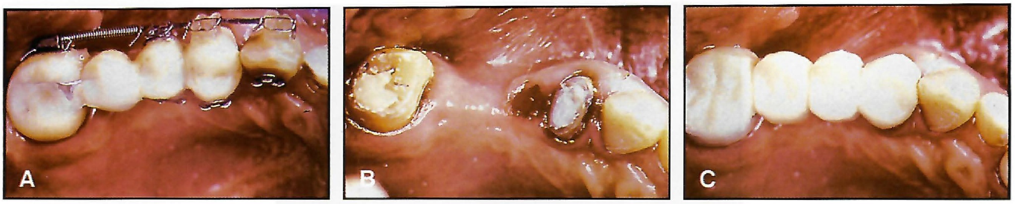
Fig. 14 Case 2. A. After retraction. B. Removal of Spider Screw. C. Final prosthetic reconstruction.
Case 3
This 45-year-old female's upper midline was deviated to the right, with anterior spacing (Fig. 15). Both upper first molars were missing, and the upper second molars were tipped mesially. She had a Class I canine relationship on the left and a Class III tendency on the right.
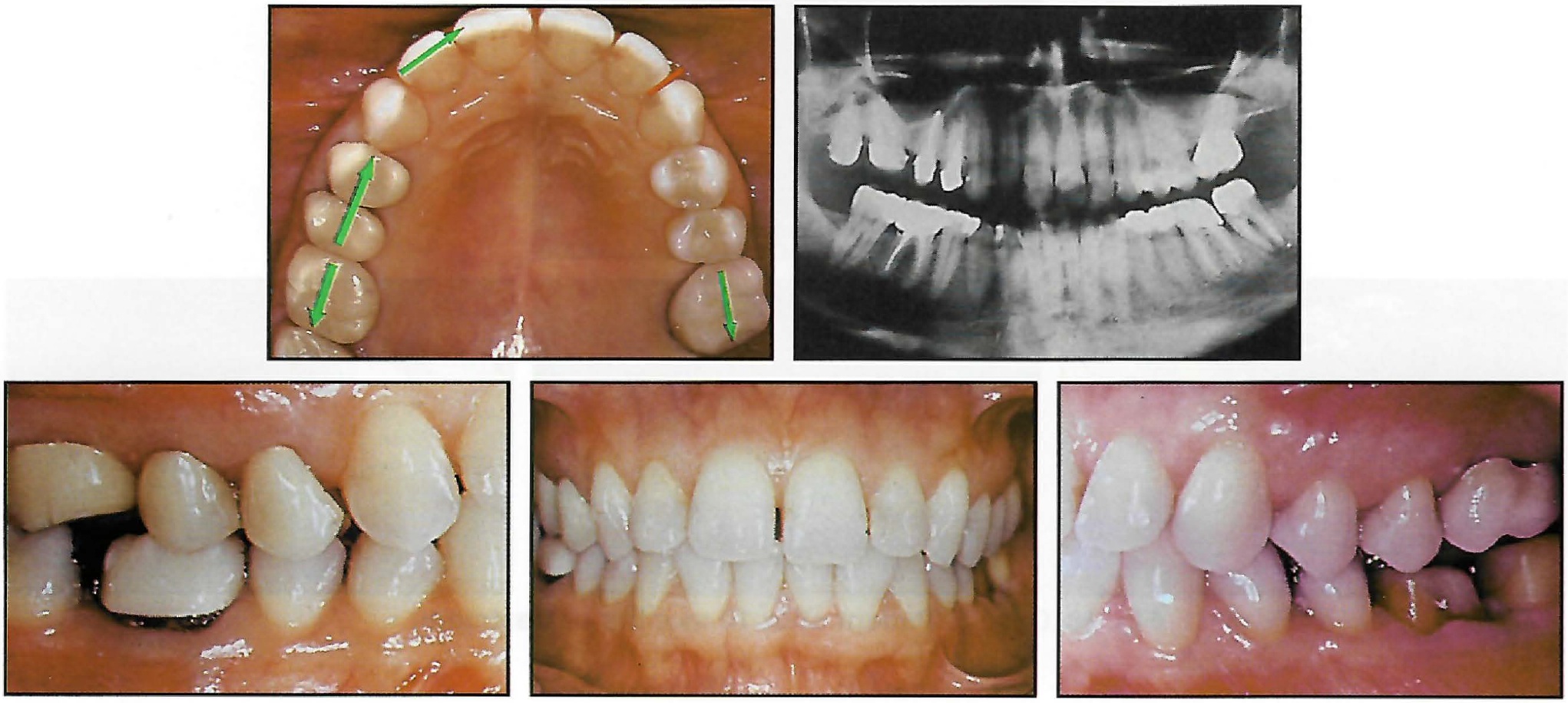
Fig. 15 Case 3. 45-year-old female with upper midline deviation and anterior spacing before treatment. Arrows show desired tooth movements.
The patient indicated that wearing extraoral appliances would be difficult, and she chose not to have brackets in the lower arch, ruling out anchorage with Class II elastics. The upper right third molar was extracted, and a Spider Screw was inserted in the buccal plate between the upper left second premolar and second molar (Fig. 16). Brackets were bonded to the maxillary teeth. An .016" × .022" stainless steel archwire was inserted, with two 150g Sentalloy open-coil springs attached between the upper second premolars and second molars to upright the second molars and reopen the first molar spaces.
An .012" stainless steel ligature wire was placed from the Spider Screw to the upper left canine to dissipate the reaction force from the coil spring and prevent mesial movement of the premolars and canine (Fig. 17). On the right side, the reaction force moved the premolars and canines into a Class I relationship, closing the anterior spaces and correcting the midline deviation.
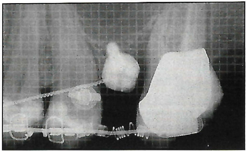
Fig. 16 Case 3. Insertion of Spider Screw.
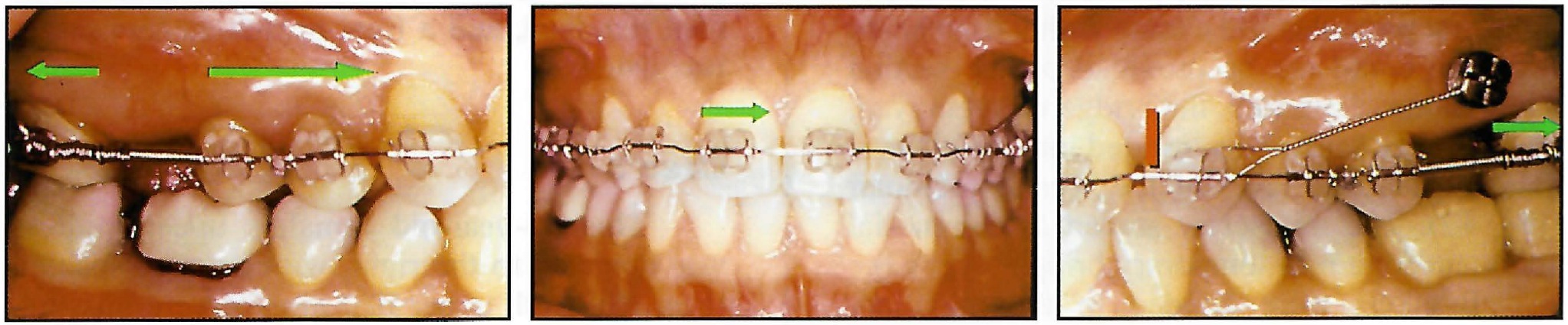
Fig. 17 Case 3. Orthodontic appliance, with anchorage provided by Spider Screw on left side.
Interproximal stripping was performed in the mandibular arch, and a spring aligner was used to correct the mild crowding. Total treatment time was 10 months (Fig. 18).
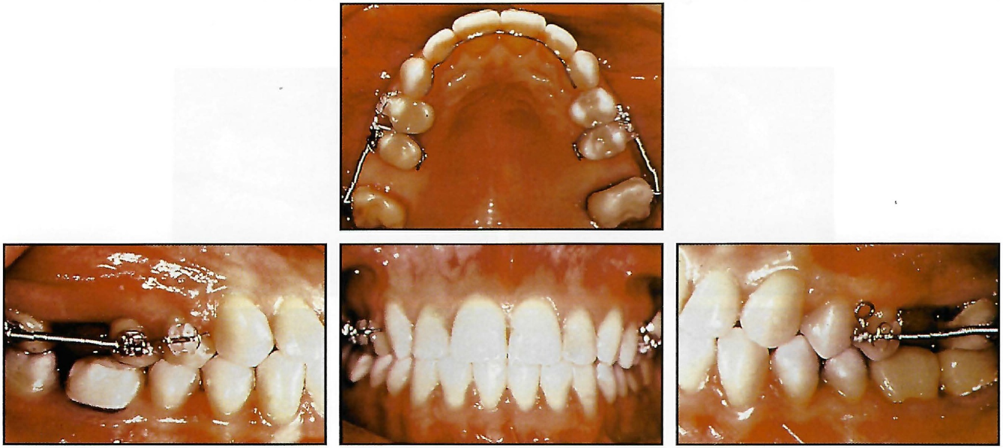
Fig. 18 Case 3. Patient after 10 months of treatment.
Conclusion
Spider Screws can be used to support different types of orthodontic mechanics, especially in cases with incomplete arches or limited cooperation, as shown here. Their ease of application and small size also permit their use in patients with intact dentitions when anchorage recovery is necessary during treatment.
FOOTNOTES
- *Trademark of HDC Company, Via dell’Industria 11, 36016 Sarcedo, Italy; e-mail: hdc@goldnet.it.
- **Trademark of GAC International, Inc., 185 Oval Drive, Islandia, NY 11749.
REFERENCES
- 1. Weinstein, S.; Haak, D.C.; Morris, L.Y.; Snyder, B.B.; and Attaway, H.E.: One equilibrium theory of tooth position, Angle Orthod. 33:1-26, 1963.
- 2. Pilon, J.J.G.M.; Kuijpers-Jagtman, A.M.; and Maltha, J.C.: Magnitude of orthodontic forces and rate of bodily tooth movement: An experimental study, Am. J. Orthod. 110:16-23, 1996.
- 3. Umemori, M.; Sugawara, J.; Mitani, H.; Nagasaka, H.; and Kawamura, H.: Skeletal anchorage system for open-bite correction, Am. J. Orthod. 115:166-174, 1999.
- 4. Roberts, W.E.; Nelson, C.L.; and Goodacre, C.J.: Rigid implant anchorage to close a mandibular first molar extraction site, J. Clin. Orthod. 28:693-704, 1994.
- 5. Kanomi, R.: Mini-implant for orthodontic anchorage, J. Clin. Orthod. 31:763-767, 1997.
- 6. Melsen, B. and Verna, C.: A rational approach to orthodontic anchorage, Progress Orthod. 1:11-22, 2000.
- 7. Higuchi, K.W. and Slack, J.M.: The use of titanium fixtures for intraoral anchorage to facilitate orthodontic tooth movement, Int. J. Oral Maxillofac. Implants 6:338-344, 1991.
- 8. Costa, A.; Dalstra, M.; and Melsen, B.: L’Aarhus anchorage system, Ort. It. 9:487-496, 2000.
- 9. Ohmae, M.; Saito, S.; Morohashi, T.; Seki, K.; Qu, H.; Kanomi, R.; Yamasaki, K.; Okano, T.; Yamada, S.; and Shibasaki, Y.: A clinical and histological evaluation of titanium miniimplants as anchors for orthodontic intrusion in the beagle dog, Am. J. Orthod. 119:489-497, 2001.
- 10. Boyd, R.L.; Leggott, P.J.; Quinn, R.S.; Eakle, W.S.; and Chambers, D.: Periodontal implications of orthodontic treatment in adults with reduced or normal periodontal tissue vs. those of adolescents, Am. J. Orthod. 96:191-198, 1989.
-
 DR. MAINO
 -
 DR. BEDNAR
 -
 DR. PAGIN
 -
 DR. MURA
Dr. Maino is a Visiting Professor at Parma University and in the private practice of orthodontics at Viale Milano 53, 36100 Vicenza, Italy; e-mail: vicenza@mainog.com. Dr. Bednar is an Assistant Professor, Department of Orthodontics, Boston University School of Dental Medicine, and in the private practice of orthodontics in Nashua, NH. Dr. Pagin is in the private practice of orthodontics in Bologna, Italy, and Dr. Mura in Vicenza, Italy.