The Connecticut Intrusion Arch
Correction of deep overbite in conjunction with a Class II molar relationship may be accomplished by anterior intrusion, posterior extrusion, or a combination of both. The decision must be based on the ideal incisor position, considering lip-to-tooth relationships and the lower vertical dimension.1,2
Although numerous methods have been described for incisor intrusion, Begg,3 Ricketts,4,5 and Burstone6 employ the same basic principle: tipback bends at the molars to provide an intrusive force at the incisors.7-9 The wire materials used for intrusion in these techniques are diverse, but all recognize the need for a light, continuous force.
The intrusion arch, as described by Burstone, is significantly different in its force delivery because it is not engaged in the incisor brackets.6,10 Properly designed and employed, an intrusion arch will tip the molars back while simultaneously intruding the incisors. A single design can correct multiple problems with no wire changes and minimal appliance adjustments.
Nickel titanium alloys are currently the materials of choice for delivering light, continuous forces under large activations.11,12 These alloys have high memory and low load-deflection rates, producing small increments of deactivation over time and thus reducing the number of reactivation appointments.
Similar articles from the archive:
- Maxillary Molar Intrusion with the Molar Intrusion Arch February 2000
- Simultaneous Intrusion and Retraction of the Anterior Teeth September 1998
- Molar Intrusion with a Removable Appliance August 1996
The present article will describe the nickel titanium Connecticut Intrusion Arch* (CTA). Although its most common use is for absolute intrusion of anterior teeth, it has many other applications, including molar tipback for Class II correction, preparation of posterior anchorage, incisor flaring, correction of minor open bites, leveling of anterior occlusal cants, and finishing.
Appliance Design
The CTA is fabricated from a nickel titanium alloy to provide the advantages of shape memory, springback, and light, continuous force distribution. It incorporates the characteristics of the utility arch as well as those of the conventional intrusion arch. The CTA is preformed with the appropriate bends necessary for easy insertion and use (Fig. 1).
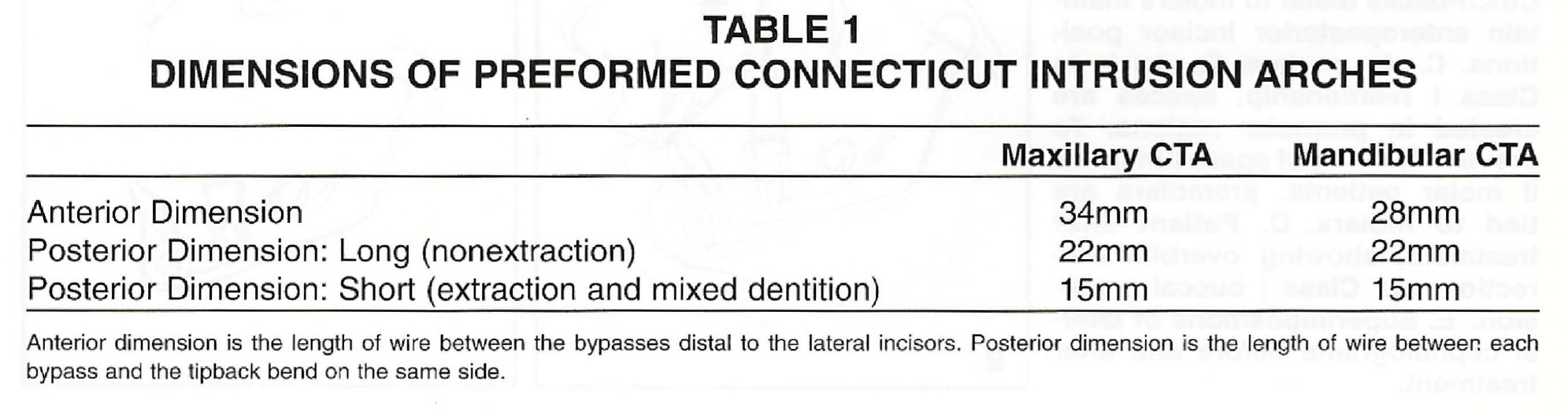
Two wire sizes are available: .016" X .022" and .017" X .025". The maxillary and mandibular versions have anterior dimensions of 34mm and 28mm, respectively. Although in most cases the wire is not directly ligated into the bracket slots, the anterior wire dimension is adequate to allow for it. The bypass, located distal to the lateral incisors, is available in two different lengths to accommodate for extraction, nonextraction, and mixed dentition cases (Table 1).
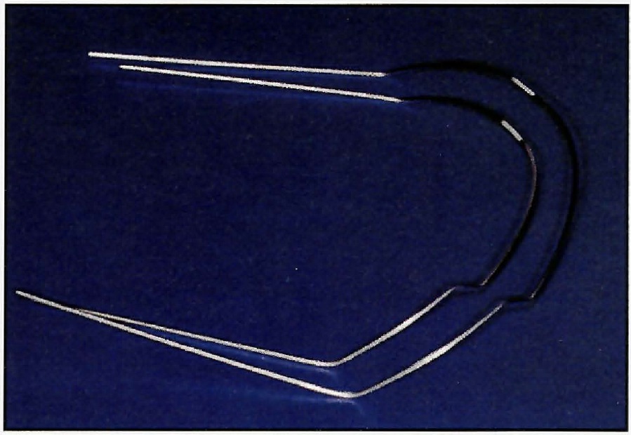
Fig. 1 Maxillary and mandibular Connecticut Intrusion Arches.
Hardware requirements are minimal. We recommend triple tubes on the maxillary molars and double tubes on the mandibular molars. An .018" X .025" auxiliary tube allows the CTA to be used in conjunction with other wires. Piggyback wires and posterior segments may be used where necessary. Transpalatal bars may be added to maintain buccal width or for anchorage purposes.
Mechanics
The CTA's basic mechanism for force delivery is a V-bend calibrated to deliver approximately 40-60g of force. Upon insertion, the V-bend lies just anterior to the molar brackets. When the arch is activated, a simple force system results, consisting of a vertical force in the anterior region and a moment in the posterior region (Fig. 2).
Incisor intrusion requires about 50g of force directed apically along the center of resistance. Although the CTA is calibrated for this purpose, slight differences in placement may alter the force system during activation. The moment created at the molar will also vary, according to the amount of force at the incisors multiplied by the distance to the molars. These minor changes can be measured with a spring gauge when the arch is inserted, and the necessary adjustments can be made to ensure proper force delivery.
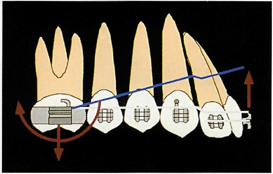
Fig. 2 Intrusion force system consists of anterior intrusive force, posterior extrusive force, and posterior tipback moment.
About 1mm of intrusion can be expected every six weeks. It is important to watch for side effects on the molars, and to use headgear to counteract these effects and correct molar root positions as needed. Patient compliance is generally not a problem, since headgear is worn for only a few months.
Incisor Intrusion
With proper diagnosis and treatment planning, the CTA can rapidly correct a deep overbite and Class II molar relationship, requiring a minimal number of appliance adjustments (Fig. 3).
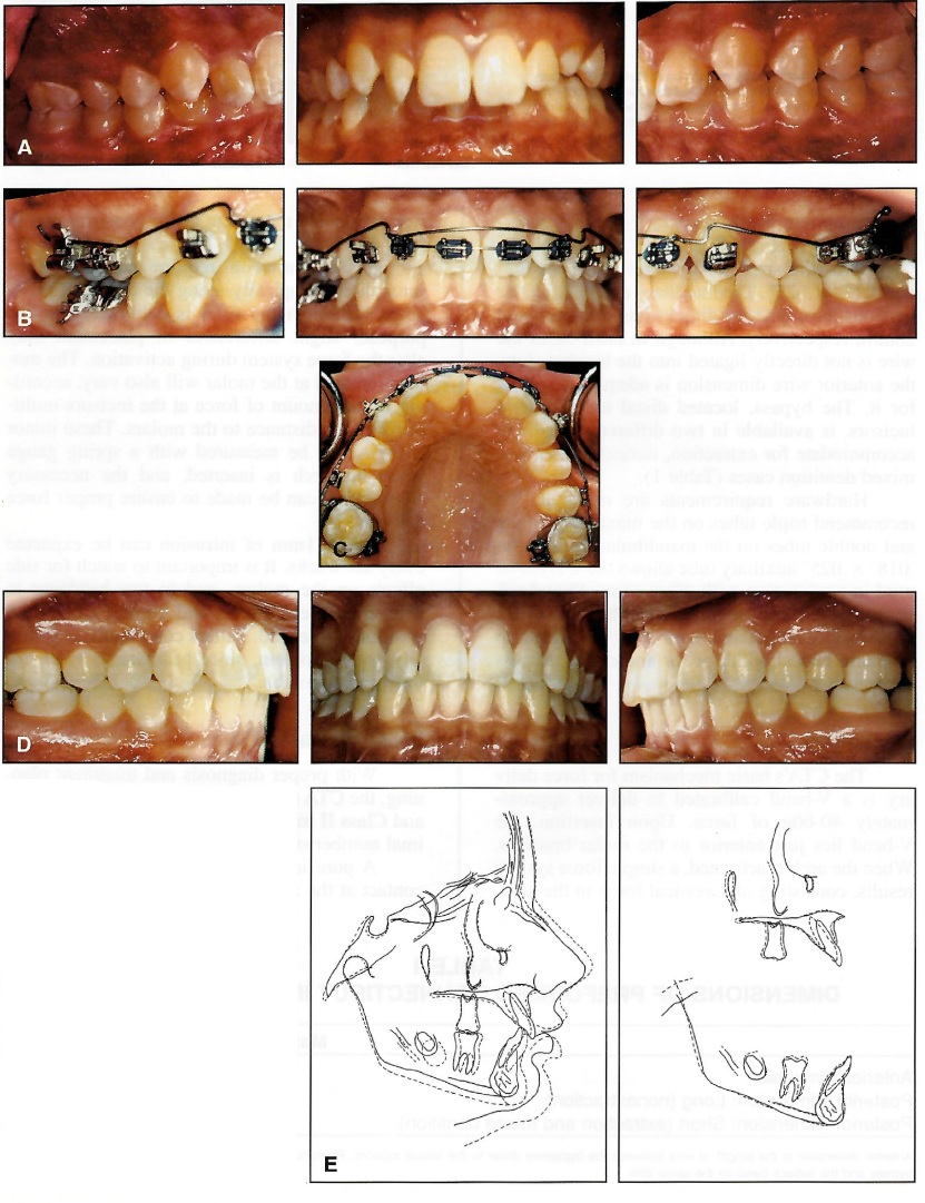
Fig. 3 A. Patient requiring intrusion of maxillary incisors, treated without extractions. B. CTA tied to anterior segment only at lateral incisors because of incisor protrusion. If incisors had not been protrusive, CTA would also have been ligated between central incisors. Cinch-backs distal to molars maintain anteroposterior incisor positions. C. As molars tip back to Class I relationship, spaces are created in premolar regions. To prevent opening of spaces in Class II molar patients, premolars are tied to molars. D. Patient after treatment, showing overbite correction and Class I buccal occlusion. E. Superimpositions of lateral cephalograms before and after E treatment.
A pure intrusion arch would have a point contact at the incisors. Insertion of the wire into the incisor brackets, however, will tend to flare the incisors, which may or may not be desirable. During intrusion of flared incisors, the CTA's point of force application is anterior to the center of resistance, which will flare the incisors even more unless the length of wire between them and the molars is fixed. A tight cinch-back--a sharp bend distal to the molar tube, preventing forward slippage of the wire--will prevent incisor flaring during intrusion and produce some retraction of the incisors during molar tipback. The cinch-back bend can be placed in a number of ways, including:
- Flaming the ends of wire, then allowing it to cool for easy bending
- Grabbing the wire with a ligature director and twisting it sharply
- Using distal-bend or cinch-back pliers
- Adding tie-back hooks (crimped-on surgical hooks or washers, secured by ligatures)
When a Class I molar relationship already exists, the use of posterior wire segments or a transpalatal bar is recommended to minimize tipback and 3rd-order molar side effects (Fig. 4.
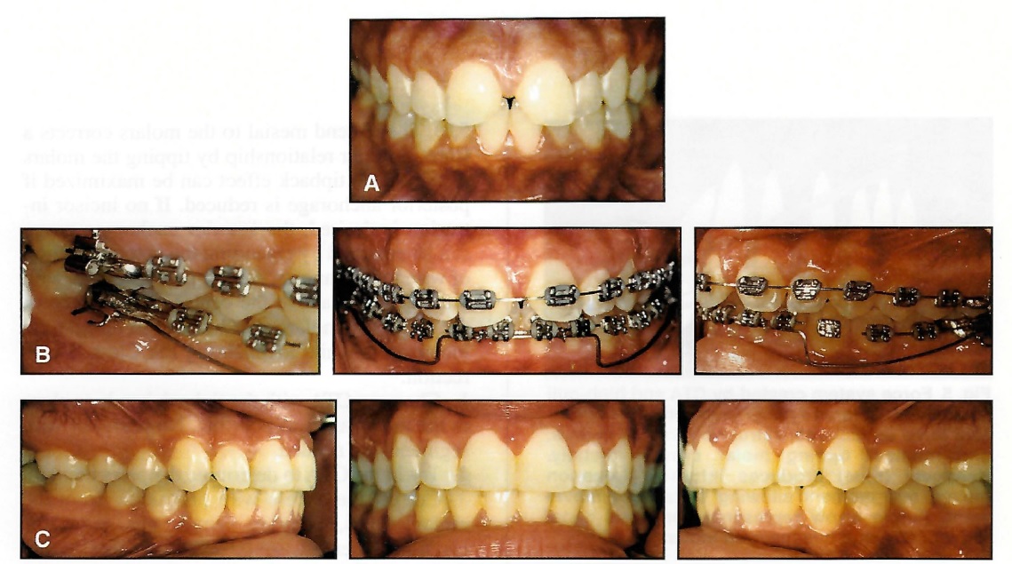
Fig. 4 A. Patient with deep overbite before treatment. Upper-lip-to-upper-incisor relationship was ideal; therefore, mandibular incisor intrusion was required. B. Mandibular CTA in place, with wire segments in posterior brackets to maintain Class I molar relationship by preventing molar tipback. C. Patient after treatment, showing correction of deep overbite and maintenance of Class I buccal occlusion. Temporary restorations were used to hold maxillary incisor positions until gingival health improved, allowing final preparations for porcelain veneers.
- Insert a section of wire into the incisor brackets.
- Choose the appropriate CTA (Long for nonextraction or Short for extraction or mixed dentition).
- Try in the CTA to determine the proper length.
- Cut off the excess wire protruding from the molar tubes, leaving 3mm per side for cinch-back bends.
- Insert the posterior legs directly into the molar auxiliary tubes.
- Tie the CTA to the anterior segment at the lateral incisors and between the central incisors.
Simultaneous Class II Molar Correction
The CTA is ideally suited for simultaneous intrusion and Class II molar correction (Figs. 5, 6. The V-bend mesial to the molars corrects a Class II molar relationship by tipping the molars distally. This tipback effect can be maximized if posterior anchorage is reduced. If no incisor intrusion is desired, the anterior anchorage group can be enlarged by extending the anterior section of wire to the canines. A high-pull headgear, with the outer bow above the center of resistance of the maxillary molars, can be used to upright the molar roots while maintaining the Class II correction.13
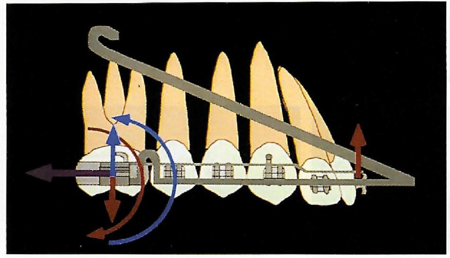
Fig. 5 Force system created by CTA and high-pull headgear. CTA force system (red) consists of intrusive force on incisors, extrusive force on molars, and moment tipping molar crowns distally. Headgear (blue) produces intrusive force on molars and moment allowing distal root movement. Purple arrow represents combined distal force of CTA and headgear on molars.
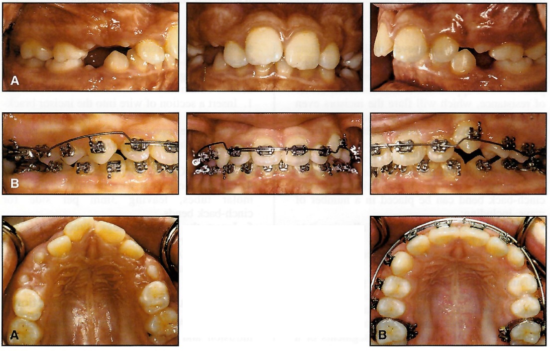
Fig. 6 A. Patient with deep bite, flared incisors, crowding, and full-cusp Class II molar relationship. B. After retraction of maxillary incisors and achievement of Class I molar relationship. CTA is then used as space-maintaining arch during eruption of posterior teeth.
- Choose a CTA with the tipback bends as close to the molar tubes as possible. No posterior wire segments are needed.
- Try in the CTA to determine the proper length.
- Cut off the excess wire protruding from the molar tubes, leaving 3mm per side for cinch-back bends.
- Insert the posterior legs directly into the molar tubes or molar auxiliary tubes.
- Tie the CTA to the anterior segment at the lateral incisors and between the central incisors.
- Cinch the wire back tightly distal to the molars.
- If the premolars have erupted and need to be moved distally, ligate them to the molars. The tipback of the CTA will prevent any anterior molar displacement.
Incisor Flaring
In patients with upright or lingually inclined incisors, the CTA can be used to flare the incisors without any side effects on adjacent teeth (Fig. 7). If the CTA is not cinched back, it will slide forward through the molar tube, and the incisors will flare. Full engagement in the incisor brackets will create a moment for lingual root torque that will flare the incisors even more. A crimped-on washer or stop advance may be added, but the low force-deflection rate of the nickel titanium wire allows a similar effect with its gentle, protrusive force against the incisors.
- Choose a CTA with the V-bends mesial to the molar tubes.
- Insert the posterior legs directly into the molar tubes, and cut off the excess wire.
- For maximum flaring, tie the CTA directly into the incisor brackets.
Correction of Minor Open Bite (Incisor Extrusion)
The reverse configuration of the intrusion arch as an extrusion arch is an obvious application that is not commonly used, partly because of side effects on the molars. When the CTA is inserted upside down, the anterior portion of the wire lies occlusal to the incisors (Fig. 8). This will extrude the incisors while creating a mesial tipping moment and an intrusive force at the molars. The molar intrusive force is desirable, but rarely clinically significant. The mesial tipping is usually undesirable, since it may worsen an open bite. To counteract this side effect, a high-pull headgear can be used, or the premolars can be incorporated into the posterior segment.
- Insert a section of wire into the incisor brackets.
- Choose the appropriate CTA (Long for nonextraction or Short for extraction or mixed dentition).
- Increase posterior anchorage if tip-forward and 3rd-order molar side effects are not desired.
- Try in the CTA to determination the proper length.
- Cut off the excess wire protruding from the molar tubes.
- Insert the CTA upside down, with the apex of the V-bend pointing gingivally and the posterior legs entering directly into the molar tubes or molar auxiliary tubes.
- Tie the CTA incisal to the anterior segment at the lateral incisors and between the central incisors.
Correction of Anterior Occlusal Cant
In planning for the correction of anterior occlusal cants, the offending teeth must first be identified, and then the mode of correction--intrusion or extrusion--must be selected. For example, if only two incisors were supererupted and needed to be intruded, it would not be necessary to tie all four incisors to the CTA; only the offending teeth would be tied to the CTA. Anterior cants are corrected in the same way, tying in only the side that needs to be corrected (Fig. 9).
- Determine the appropriate vertical incisor position, and decide which incisors need intrusion or extrusion.
- Add a transpalatal bar if molar side effects are not desired.
- Choose a CTA with the V-bends mesial to the molar tubes.
- Try in the CTA to determine the proper length.
- Cut off the excess wire protruding from the molar tubes.
- For incisor extrusion, place the CTA with the V-bend pointing gingivally. For incisor intrusion, place the CTA with the V-bend pointing incisally.
- Insert the posterior legs directly into the molar tubes or molar auxiliary tubes.
- Tie the CTA only to the brackets of the incisors to be leveled.
- For correction of an anterior cant, use a 2-2 wire segment, and tie the CTA only to the side to be corrected.
Conclusion
The Connecticut Intrusion Arch is a multifunctional wire that is preformed from nickel titanium and provides the high performance and mechanical advantages of these alloys. Although incisor intrusion is its most common application, various other functions can easily be performed with only minor modifications.
The CTA will remain active at a constant force level for a long period of time, allowing long intervals between appointments and virtually eliminating the need for adjustments. Its simplicity of design and minimal requirement for auxiliary hardware make it an ideal addition to the armamentarium of the busy clinician.
FOOTNOTES
- *Distributed by Ortho Organizers, Inc., GAC International, Inc., Masel, and ClassOne Orthodontics.
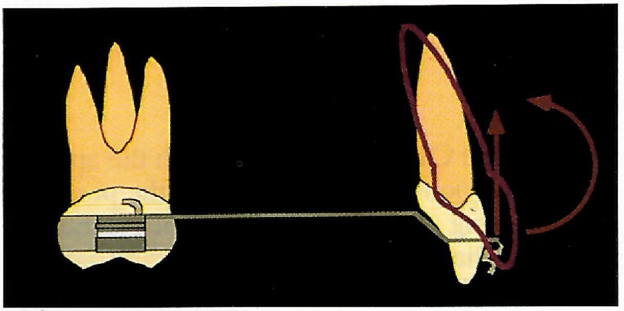
Fig. 7 Force system for incisor flaring. CTA is not cinched back, and can be ligated directly into incisor brackets for maximum flaring.
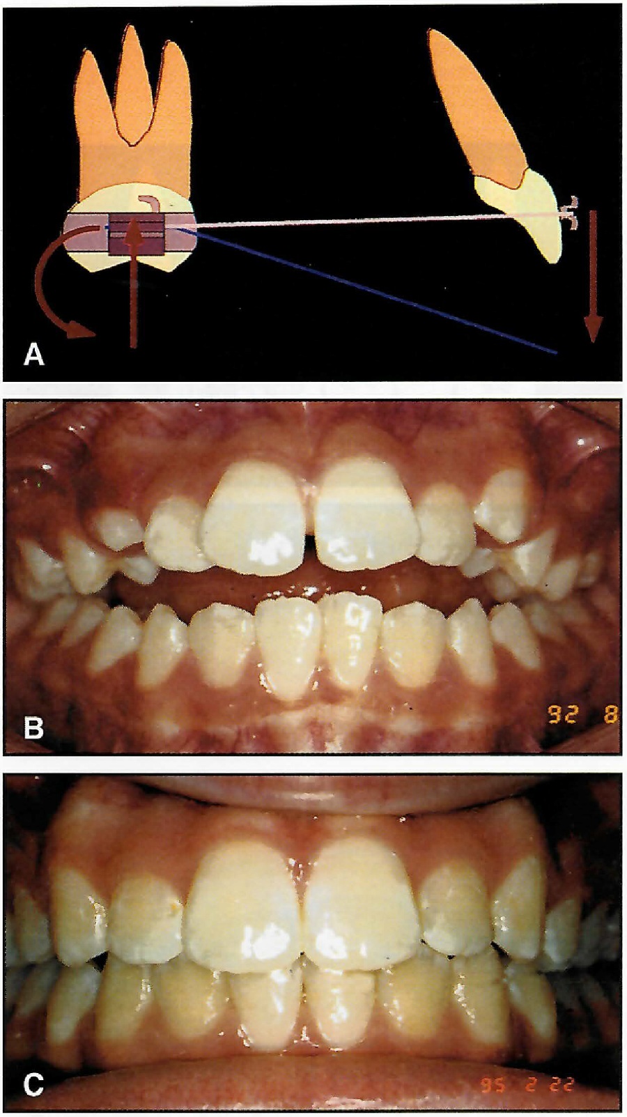
Fig. 8 A. Force system for incisor extrusion, with CTA is inserted into molar brackets upside down. Vertical forces shown are ideal for correction of minor open bites. B. Open-bite patient before treatment. C. Mechanics shown in A used to close bite, with high-pull headgear added to prevent forward tipping of molars and augment intrusive force of CTA on molars.
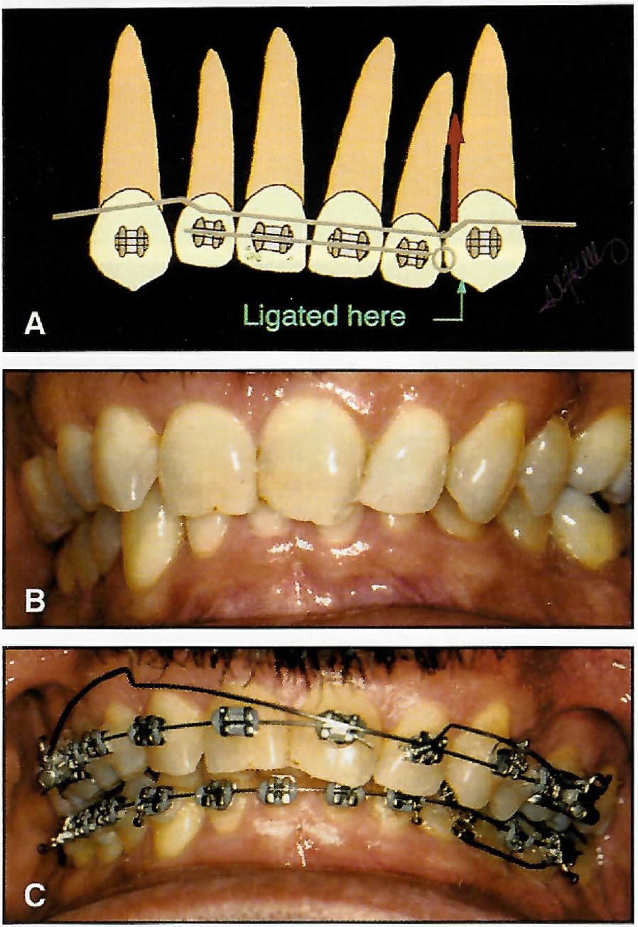
Fig. 9 A. Force system for correction of anterior cant of occlusal plane, using asymmetrical ligation of CTA. B. Patient with anterior occlusal cant before treatment. C. CTA using mechanics shown in A.
REFERENCES
- 1. Nanda, R.: The differential diagnosis and treatment of excessive overbite, Dent. Clin. N. Am. 25:69-84, 1981.
- 2. Lindauer, S.J.: Orthodontic treatment planning, in Biomechanics in Clinical Orthodontics, ed. R. Nanda, W.B. Saunders Co., Philadelphia, 1997, pp. 23-49.
- 3. Begg, P.R. and Kesling, P.C.: Begg Orthodontic Theory and Technique, W.B. Saunders Co., Philadelphia, 1977, pp. 203-214.
- 4. Ricketts, R.M.: Bioprogressive therapy as an answer to orthodontic needs: Part I, Am. J. Orthod. 70:241-248, 1976.
- 5. Ricketts, R.M.: Bioprogressive therapy as an answer to orthodontic needs: Part II, Am. J. Orthod. 70:359-397, 1976.
- 6. Burstone, C.J.: Deep overbite correction by intrusion, Am. J. Orthod. 72:1-22, 1977.
- 7. Shroff, B. and Nanda, R.: Biomechanics of Class II correction, in Biomechanics in Clinical Orthodontics, ed. R. Nanda, W.B. Saunders Co., Philadelphia, 1997, pp. 143-155.
- 8. Romeo, D.A. and Burstone, C.J.: Tipback mechanics, Am. J. Orthod. 72:414-421, 1977.
- 9. Mulligan, T.F.: Common Sense Mechanics, CSM Publishing, Phoenix, 1982.
- 10. Nanda, R.: Correction of deep overbite in adults, Dent. Clin. N. Am. 40:67-87, 1997.
- 11. Burstone, C.J.: Variable-modulus orthodontics, Am. J. Orthod. 80:1-16, 1981.
- 12. Kusy, R.P.: A review of contemporary archwires: Their properties and characteristics, Angle Orthod. 67:197-208, 1997.
- 13. Siatkowski, R.E.: The role of headgear in Class II dental and skeletal corrections, in Biomechanics in Clinical Orthodontics, ed. R. Nanda, W.B. Saunders Co., Philadelphia, 1997, pp. 109-142.
-
 DR. NANDA
 -
 DR. MARZBAN
 -
 DR. KUHLBERG
Dr. Nanda is Professor, Head, and Program Director, Dr. Marzban is a third-year resident, and Dr. Kuhlberg is Assistant Professor and Clinic Director, Department of Orthodontics, School of Dentistry, University of Connecticut Health Center, 263 Farmington Ave., Farmington, CT 06030.