Clinical Management of the Frankel FR II Appliance
In the early years of the Frankel appliance, clinicians and laboratories in this country were unsure of the design, fit, adjustment, and management of the appliance. Poorly fitting appliances were placed. Teeth were left unnotched. Little attention was paid to lip seal. Many of the mistakes were thought to be improvements, but, after several clinical failures or minimal treatment responses, most clinicians have realized that Frankel's design ideas appear to be correct.
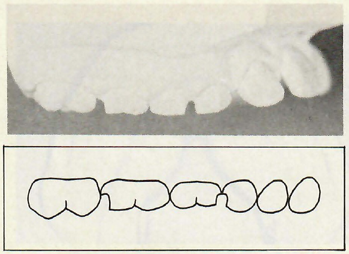
Notching
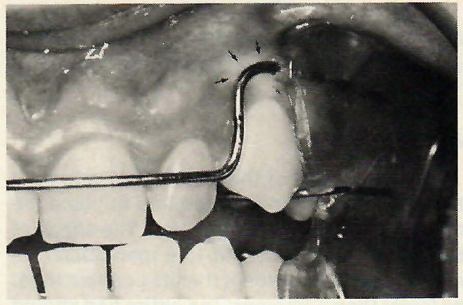
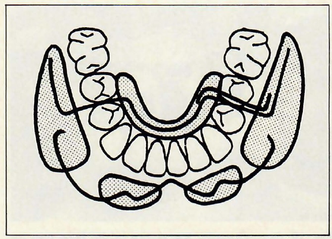
Proper design of the FR II appliance must begin with adequate notching of the maxillary deciduous teeth. The purposes of notching are:
1. to provide a positive seat for the appliance, making it easier to wear,
2. to prevent the appliance from slipping distally during sleep, which would tend to lessen the desired muscular response and rabbit the maxillary incisors due to contact of the labial bow,
3. to prevent eruption of the maxillary posterior teeth and contribute to Class II correction.
Too little notching will not accomplish these purposes. However, it is not necessary to notch the teeth through to the gingiva, which may allow the appliance to overseat and make the gingiva sore. Notched steps (Fig. 1) permit the orthodontist to perform this procedure prior to taking the impressions, rather than having the laboratory perform this step on the model, and avoid the loss of notch space either while the appliance is being made or subsequently during treatment. Only deciduous teeth should be notched. A #1558 S.S. White crosscut fissure bur is ideal for notching, and high speed notching is far more comfortable than low speed. In the permanent dentition, separators can be used to gain the positive seating of the appliance, although the wires will frequently seat without separation because of the steep embrasures of newly erupted teeth.
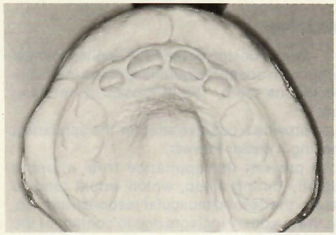
Impressions
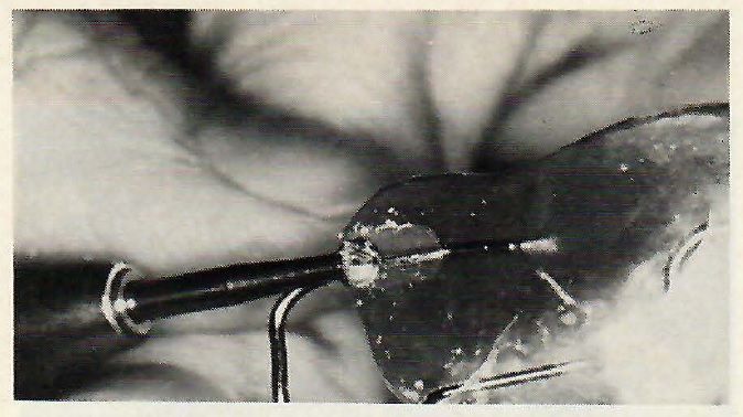
The next step is to obtain proper impressions. Overextended impressions, commonly taken for study models, are not suitable for a properly fitting appliance, because there is too much soft tissue distortion at the depth of the vestibule. The more alginate that rolls out of the tray, the more soft tissue distortion that occurs (Fig. 2). The more soft tissue distortion that occurs, the more difficult the model trimming will be and the more likely that the appliance will not fit properly.
Acrylic Parts
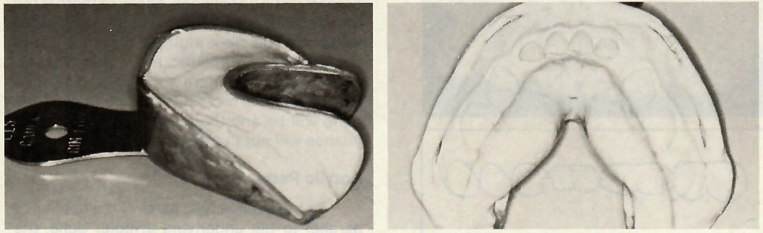
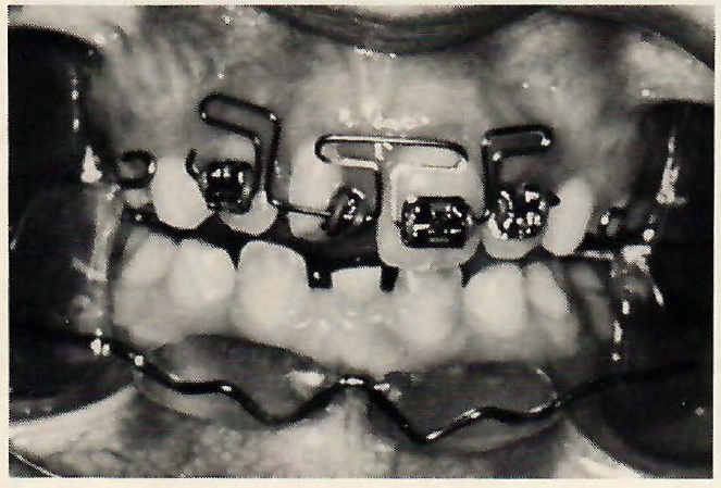
To have the acrylic parts of the appliance parallel to the underlying alveolar bone, the models are trimmed according to Frankel's recommendations1 and as reported in detail by McNamara.2 It is
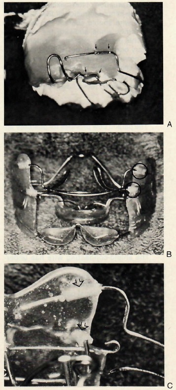
best to have the patient present when trimming the models. To eliminate the need for the patient's presence, custom trays or heat-moldable trays can be used for more accurate impressions, as suggested by McNamara.3,4 A proper Frankel impression can be made using Rim Lock trays that are underfilled with alginate (Fig. 3). Figure 4 shows the typical model trimming that is necessary when using Rim Lock trays.
Vestibular Shields
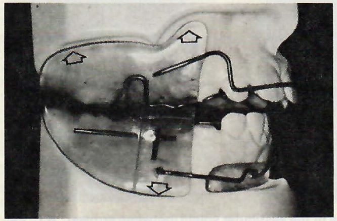
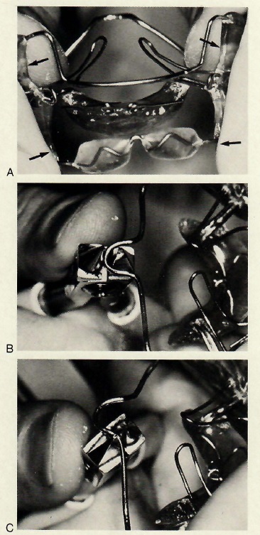
The vestibular buccal shields are large pieces of acrylic that extend from the depth of the maxillary vestibule to the depth of the mandibular vestibule. They should extend as far as possible into the depth of the vestibule without causing patient discomfort (Fig. 5). The purpose of the shields is to:
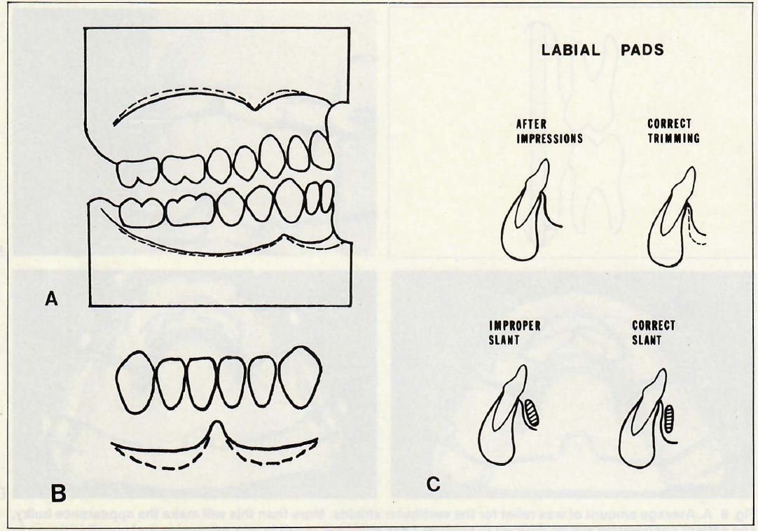
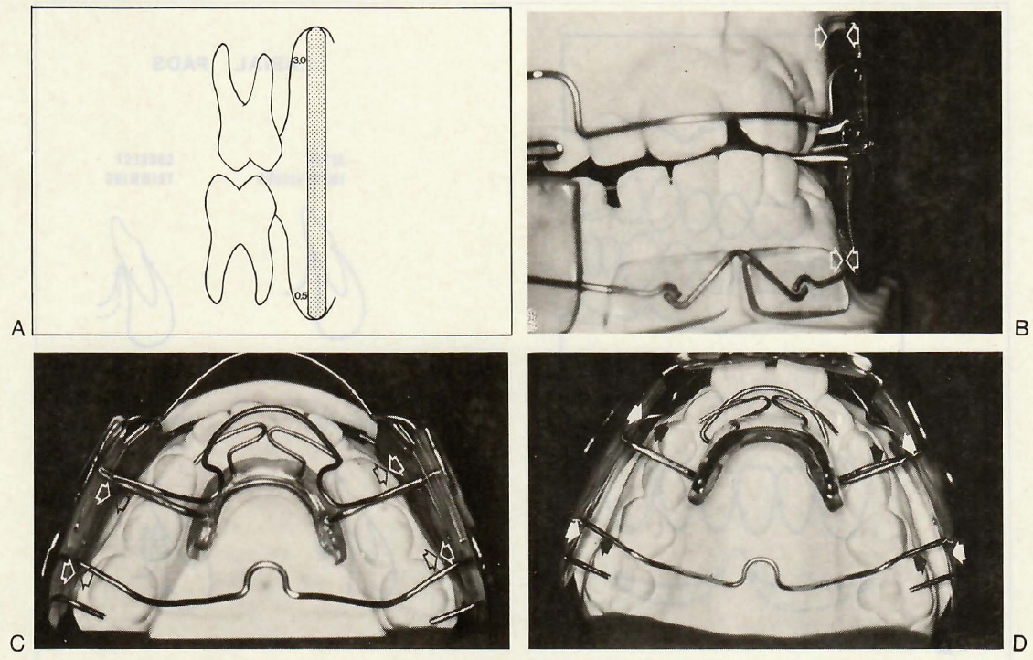
The shields should be approximately 2.5mm thick, and the edges must be rounded similar to a denture. They should have approximately 3mm of relief from the alveolar tissues on the maxilla and 0.5mm relief from the tissues on the mandible (Fig. 6). They are made straight up and down, allowing for more dental expansion than bone expansion, which saves remaking the appliance too early in treatment.
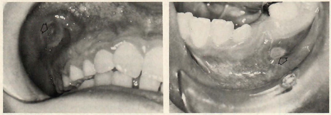
Too much relief of the buccal shields will cause the patient to look like a chipmunk (Fig. 7). This bulky appearance discourages full-time wear, which is necessary for optimal results. Edges that are left too sharp or too square tend to cause ulcers. Shields that are underextended reduce the chance for maximum expansion. Shields that are left overextended will result in tissue irritation and ulceration (Fig. 8).
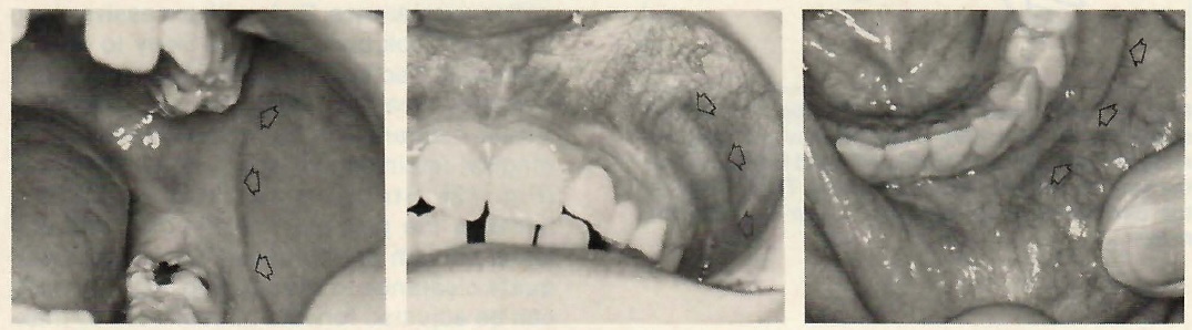
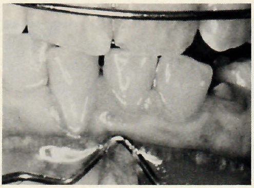
Proper extension of the shields into the vestibule results in Frankel wear marks (Fig. 9), which are reddened lines that follow the outlines of the shields. They are areas of hyperemia apparently resulting from the tension created by the shields. Presence of these lines is evidence of a properly fitting appliance and good wear time.
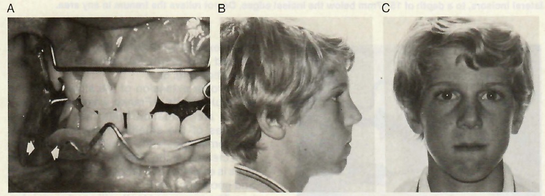
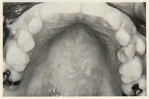
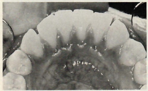
The permanent teeth will erupt more laterally than normal in patients who are wearing a well-fitted appliance properly (Fig. 10).
Labial Pads
The purpose of the labial pads is to:
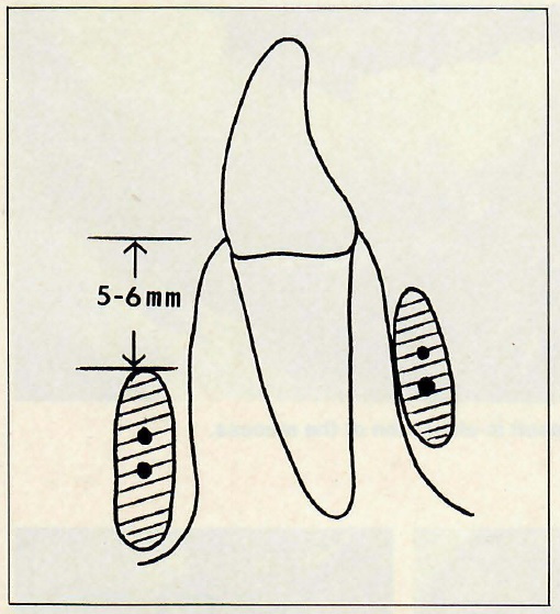
McNamara2,3 has shown the proper position of the inferior edge of the labial pads to be 10-14mm below the free gingival margin of the lower incisors. Another way to decribe their position is that the superior border of the pad should be 5-6mm below the gingival margin1 (Fig. 11). Labial pads are not lip bumpers. Lip bumpers act in the area of the orbicularis oris, while labial pads act on the mentalis muscle. This should be borne in mind during their fabrication and clinical adjustment.
Proper model trimming for the labial pads is most important, as the labial pads are the most difficult part of the appliance to fit correctly. If the models are not carved to the proper contour, an improper slant may result that can cause ulcers and gingival stripping. Figure 4 shows the labial pads in good position. Many patients cannot tolerate the ideal position initially, but the pads can be adjusted downward within a month or so.
The cross-section of the pad should have a teardrop shape, according to McNamara.4 This gives the pad more tissue clearance at the superior border and reduces the chance for gingival stripping. The pads should have 1mm of tissue clearance. Pads with excessive clearance will look bulky and are likely to reduce wear time because the patient is less attractive when wearing the appliance (Fig. 7). If the tissue clearance is too close, there will be gingival impingement and possible stripping (Fig. 12). Stripping can also be caused because the pad was not trimmed and polished enough on the tissue side to give adequate clearance to the pad (Fig. 13). The pads can be adjusted forward or backward by making the appropriate cuts into the buccal shields and moving the connecting wires (Fig. 14).
Lingual Pad
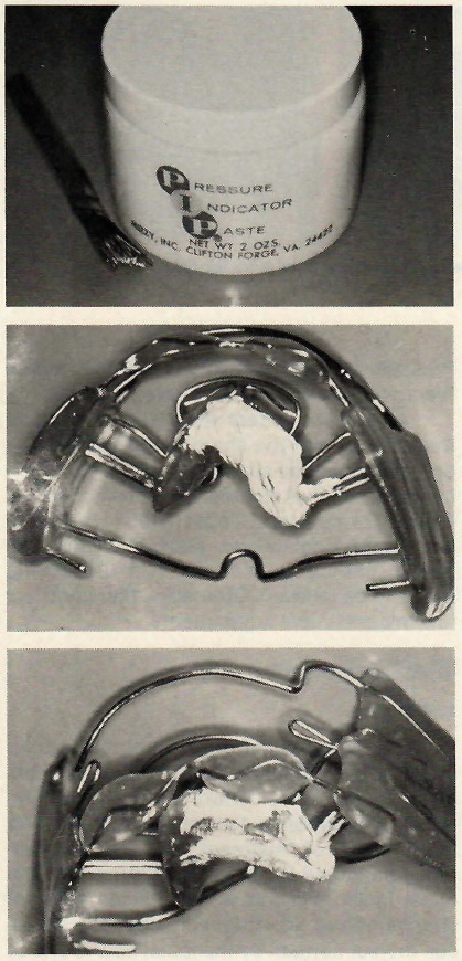
The purpose of the lingual pad is to hold the various wires in position and to place the mandible in the desired position. The shape of the lingual pad is similar to a mandibular removable retainer, except that its position must be lower than a retainer. The entire pad should be below the attached gingiva (Fig. 10). If the pad is too high, as the mandible tends to sag posteriorly at night, there will be pressure on the gingiva causing stripping (Fig. 15). If the pad is too low, the lingual frenum may become irritated, but this is not a common problem. Pressure indicator paste can be used to locate the areas that should be relieved (Fig. 16).
All acrylic borders should be rounded so that they are not too sharp or too square. The borders should be similar to a denture border, but not as thick. Adjustments of the acrylic are mainly for comfort. Occasionally, the teeth and supporting tissues expand so that the acrylic impinges on them, and the acrylic needs to be relieved. Otherwise, there are very few major clinical adjustments.
Wire Components
Labial Bow
The purpose of the labial bow is to stabilize the appliance, not to retract the maxillary incisors or to control these teeth. If the labial bow contacts the incisor teeth during the first half of treatment,
they may inadvertently be tipped lingually. Rabbitting in of the upper incisors in this way produces a dental change before an orthopedic change can occur. Incisor contact by the labial bow is one of the most frequent errors with any FJO appliance.
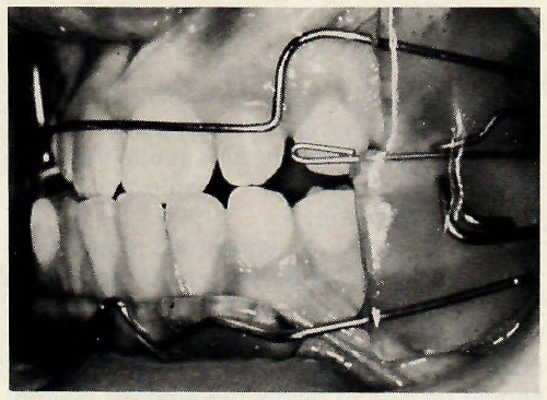
The labial bow is usually made of .036" wire. The vertical height of the wire is 11-12mm and the tissue clearance should be 2-3mm. If the wire is closer to the tissues, there is likely to be impingement and ulceration as the maxillary canines erupt (Fig. 17). The wire can be moved labially by removing lateral acrylic, bending the wire labially in the shield, placing new acrylic in the more labial position, and removing the original acrylic from the inside of the shield (Fig. 18).
Breakage is a common, but not serious, problem with the labial bow. Since the bow serves only to stabilize the appliance and only becomes active near the end of treatment, if at all, removing the entire bow does not compromise the action of the appliance (Fig. 19).Several patients in my practice have completed treatment without the labial bow, and there were no shortcomings in the treatment. However, loss of the wire sometimes worries the patient. To minimize the breakage, clear vinyl tubes are placed around the wire for 3-4mm into the acrylic (Fig. 20). These plastic tubes allow movement of the wire to be reduced gradually to zero, rather than suddenly at the edge of the acrylic. Breakage in appliances with plastic tubes has been about 1%.
Lingual Bow
The lingual bow was originally called the protrusion bow by Frankel,1,5 but, since it is rarely used to procline incisors today, the name lingual bow is more appropriate. It is usually made of .032" wire, and crosses between the deciduous canine and first molar (Fig. 6D). While it does not touch the cingulum of the incisor teeth, the wire can be placed on the cingulum if vertical eruption of the incisors needs to be arrested. The wire should clear the palate by 1-2mm.
The purpose of the lingual bow is to:
The wire should contact the deciduous molar firmly, while allowing the canine to erupt. This provides posterior traction on the maxillary buccal teeth and contributes to the overall correction. The most common problem with the lingual bow is breakage, so the vinyl tubes are used in the same manner as on the labial bow. These tubes have reduced breakage to 5%.
Palatal Bow
The palatal bow provides for posterior appliance stability and prevents the eruption of the maxillary posterior teeth. It is made of .050" wire and crosses from the palate to the vestibular shield mesial to the first molar. There is an omega-like bend in the midline to allow for limited adjustment. The wire should clear the palatal tissue by 1-2mm to avoid impingement. Tissue
impingement and breakage are the most common problems with the palatal bow. However, neither problem is frequent enough to be a major concern.
Shield-Connecting Wire
The shield-connecting wire has undergone the most extensive modification of the entire appliance design from Frankel's original recommendations. Originally, this wire ended in the lingual pad, and a separate body wire was placed in the lingual pad to cross the midline and strengthen the acrylic. Today, a single wire emanates from one buccal shield, passes through the lingual pad, and ends in the opposite buccal shield (Fig. 21).
This one-wire design has reduced breakage in the lingual pad significantly. The wire can be a single .051" wire or two .045" wires, with the second wire being a short section to reinforce the main wire. The main wire in the shield must be parallel to the occlusal plane, so that the appliance can be set forward properly. This wire does not touch any teeth. If it touches the mandibular teeth, the chances of inadvertently proclining the incisors is increased. Dumping the incisors forward would result, as the wire would hold its position while the mandible would seek to return to its rest position, especially at night. Proclination of the lower incisors has been one of the main complaints against the FJO appliances.
The most common problem with the shield connecting wire is breakage. With the two-wire design, breakage is less than 5%. Occasionally, one wire will fracture, but the second wire is adequate to hold the appliance together. There used to be frequent repairs on this wire, but the repairs rarely held and a new appliance was often necessary.
Labial Pad Connecting Wire
The labial pad connection can be a single wire or three wires. A single wire seems to be adequate, as breakage is rare. The wire is usually .036" and should travel into the shield only as far as the shield-connecting wire crossover. Carrying the wire farther into the shield makes setting the appliance forward much more difficult. The wire must be low enough to allow for proper placement of the labial pads, but it must also give adequate clearance to the frenum. These wires occasionally cause tissue impingement on the erupting canine, so they should clear the tissues by 2mm. There is very little that can be done if the erupting canine is being restricted by this wire.
Major Clinical Adjustments
Labial Pad Adjustment
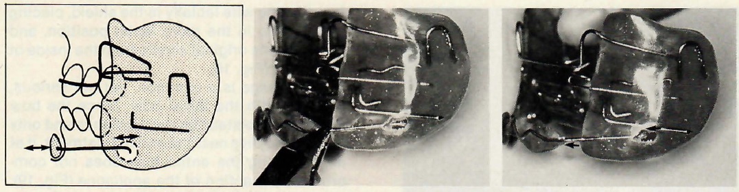
The labial pads can be adjusted to be lower, higher, closer to the tissues, or farther away from the tissues, and to change the angulation. The height of the pads and the slant can be adjusted with thumb and finger pressure. Changing the tissue clearance requires cutting out the acrylic around the connecting wire (Fig. 14).
Setting the Appliance Forward
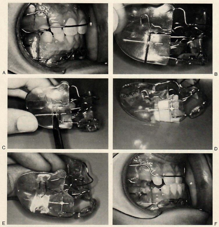
When the patient has an overjet of 6mm or more, Frankel1,5 recommends advancing the mandible in increments of 3-4mm. The labial and lingual pads can be advanced by cutting through the vestibular shield with a horizontal cut between the shield-connecting wire and the lingual bow, and a vertical cut perpendicular to the horizontal cut (Fig. 22). Do not cut through any wires, as the wires hold the appliance together. Using a laboratory knife as a wedge, advance the anterior portion of the appliance the desired amount and fill in the void with acrylic. If necessary, this procedure can be repeated.
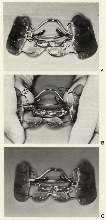
Expanding the Appliance
Widening the appliance is a very limited adjustment, but frequently necessary. As the maxillary canines and premolars erupt in a more lateral path, these teeth and their supporting tissues often impinge on the vestibular shields. Figure 23 shows the shields being widened, using thumb pressure and compensating adjustment of the palatal bow. This adjustment is limited, however, because the mandibular portion of the shields is constricted as the maxillary portion is widened. An appliance that is bent can usually be straightened out with thumb and finger pressure (Fig. 24).
Most Common Clinical Errors
The most common clinical errors with the FR II appliance are:
Each of these problems can be avoided by careful attention to details.
One of the main clinical errors for all FJO appliances is failure to decompensate the dentition prior to functional treatment. The maxillary incisors are frequently retroclined, even in a Class II malocclusion. If an ideal esthetic and functional result is to be achieved, the incisors must first be proclined into an orthognathic position. The best appliance for this is the sagittal appliance.
Often, the maxillary incisors are irregular, with or without a posterior crossbite. To correct irregular incisors only, a 2X4 setup will suffice. If overerupted maxillary or mandibular incisors are not corrected prior to FJO treatment, a long face will be iatrogenically produced. The maxillary incisors are intruded when there is a gummy smile, and the mandibular incisors are intruded when the maxillary incisors have a proper relation to the upper lip. The choices for incisor alignment prior to active FJO treatment include utility arches, quadhelices, or an upper sagittal appliance.
Relatively few clinical adjustments need to be made during treatment. The clinician's main responsibilities are to make an accurate differential diagnosis, choose the appropriate appliance system, ensure proper design and fit of the appliance, and motivate the patient during treatment.