Importance of the Occlusal Plane in Virtual Treatment Planning
Orthodontic diagnosis and treatment planning have recently moved into the digital realm, to the extent that virtual treatment projections have become commonplace. Several proprietary software platforms, including Invisalign ClinCheck*, OrthoCAD iQ**, and Ormco Insignia***, allow clinicians to modify virtual models that are suspended in space on their computer screens. But there is a significant shortcoming in the basic design of the most commonly used programs: improper orientation of the occlusal plane. That is the fundamental flaw in the current process of virtual smile design.
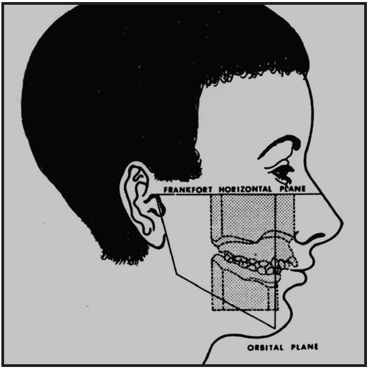
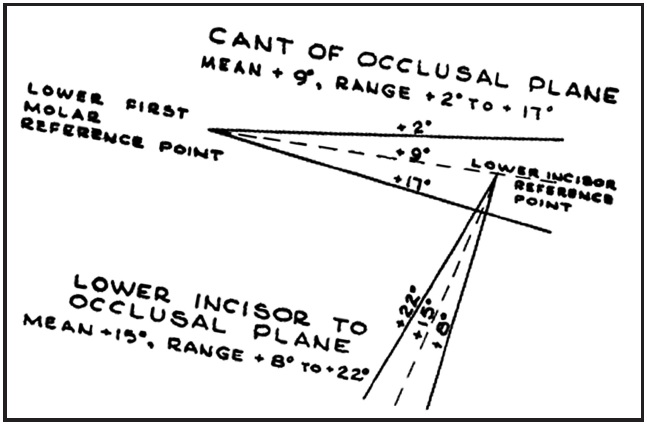
For many years, when an orthodontist trimmed diagnostic study models, the bases of the models were trimmed parallel to the Frankfort horizontal plane, and the resulting occlusal plane was thus oriented to be a true representation of the patient's actual occlusal plane angle relative to Frankfort horizontal (Fig. 1). According to Downs, that angle ranges from 2º to 17º, with a mean of about 9º (Fig. 2).2-7
Similar articles from the archive:
At some point, however, the standard changed so that study models were trimmed with the occlusal plane parallel to the floor (or desktop). That was because the upper model would frequently fall off the lower model and break if they were trimmed in the original manner. The new method of trimming orthodontic models is now the standard for ABO case presentations (Fig. 3).7
Unfortunately, when software engineers designed the currently used virtual interfaces, they based the presentation of the virtual model on the contemporary method, with the occlusal plane parallel to the floor (Fig. 4). This results in a significant loss of information about the patient's torque requirements, smile arc, and axial inclinations.
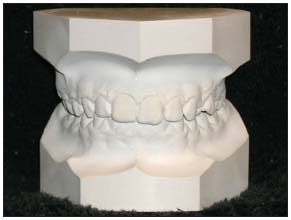
Fig. 3 Contemporary ABO standard for trimming study models.
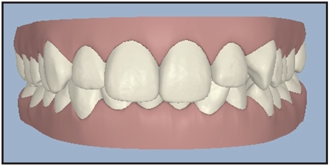
Fig. 4 Contemporary virtual model orientation.
Incisor Torque
To avoid the argument about whether Frankfort horizontal is the correct reference plane for torque calculations, let us stipulate that the most esthetic position of the upper central incisor is with a tangent to FA point perpendicular to the floor (Fig. 5).8-10 This shows just how misleading the current virtual orientation can be in terms of the occlusal plane (Fig. 6).
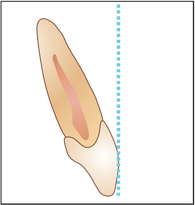
Fig. 5 Most esthetic incisor torque, with tangent to FA point perpendicular to floor.
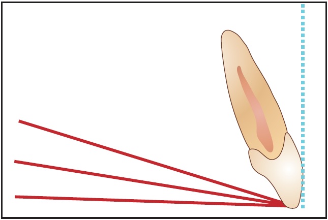
Fig. 6 Most esthetic incisor torque relative to three orientations of occlusal plane (flat, 8°, and 16°).
If the occlusal-plane-to-FA tangents for different occlusal plane angles are reoriented so that each occlusal plane is flat, it becomes obvious how much the torque of the incisors is affected (Fig. 7). If we reverse the process and set the incisor torque as desired and then reorient the virtual model to the correct occlusal plane, it is apparent that the end result is not going to be the desired result (Fig. 8).
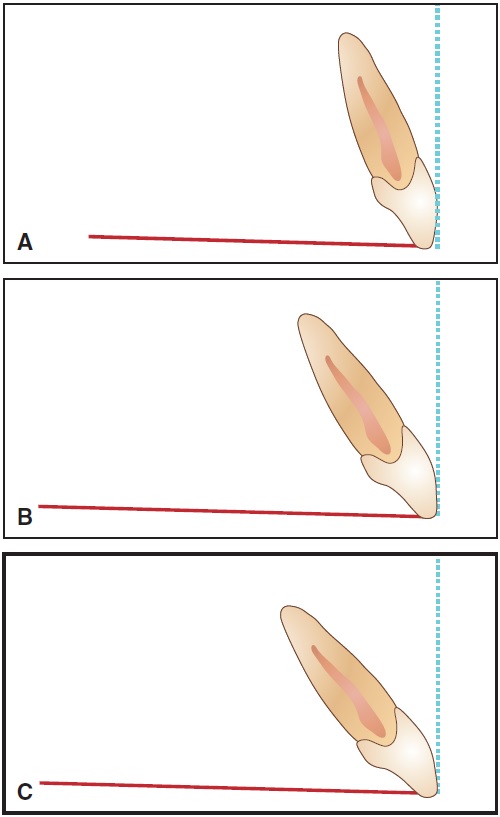
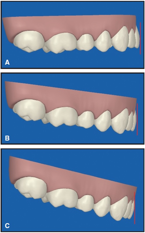
Fig. 7 Differences in incisor torque after reorientation of tangent to FA point, based on different occlusal plane angles. A. Flat. B. 8°. C. 16°.
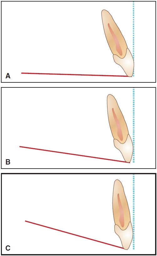
Fig. 8 Differences in incisor torque after reorientation of virtual treatment projections to actual occlusal plane angles. A. Flat. B. 8°. C. 16°.
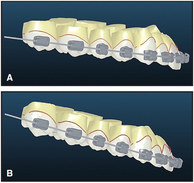
By using the common virtual method of analysis, we are simply evaluating the intended end result independent of appliances or mechanics. For example, if we were treating a patient with a 16º occlusal plane angle with Invisalign (Fig. 9), we might conclude from the retroclined orientation of the incisors at the end of treatment that the aligners were unable to express torque correctly. In reality, the aligners probably delivered the requested torque, but that torque was incorrect due to the incorrect orientation of the virtual model during treatment planning. If we were using either OrthoCAD iQ or Insignia, the recommended torque in the brackets would be incorrect, but we would have the opportunity to place additional torque in the archwire. After treatment, we might draw the invalid conclusion that the software calculated the torque incorrectly, when it was actually the virtual treatment projection that was incorrect (Fig. 10).
The Smile Arc
Sarver and others have called our attention to the importance of the smile arc as a component of an attractive smile.11,12 Parekh and colleagues have confirmed that both orthodontists and patients prefer a smile arc that is consonant with the lower lip.13 When one views the typical virtual model setup from the anterior, it becomes obvious that the orientation of the occlusal plane directly affects the resulting smile display. For instance, if the orthodontist tried to adjust the smile arc according to a virtual setup with a flat occlusal plane, but the patient actually had a 16º occlusal plane angle, the result would be an overly accentuated smile arc (Fig. 11).
Axial Inclinations
Another area in which improper virtual model orientation can detrimentally affect treatment outcomes is related to the cant, or what Ackerman and colleagues have called "roll".12 If the "roll" of the virtual model is incorrect, then the axial inclination of the incisors may be inappropriately adjusted to the wrong position.
A Temporary Solution
Until software vendors are able to orient virtual models to the true occlusal plane--through the integration of a cone-beam or cephalometric radiograph, or at least by using the mean occlusal plane angle as a default--clinicians can use a simple and straightforward method for diagnosis. With the patient's smiling facial photograph as a reference, the virtual model should be reoriented so that the cusp tips of the canines and the first molars are in the same relationship as in the photograph (Fig. 12).
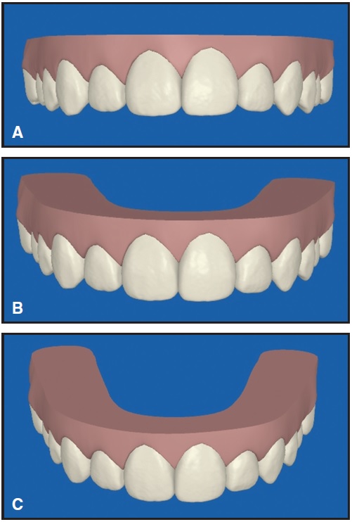
Fig. 11 Differences in smile arc in ClinCheck projections with different occlusal plane angles. A. Flat. B. 8°. C. 16°.
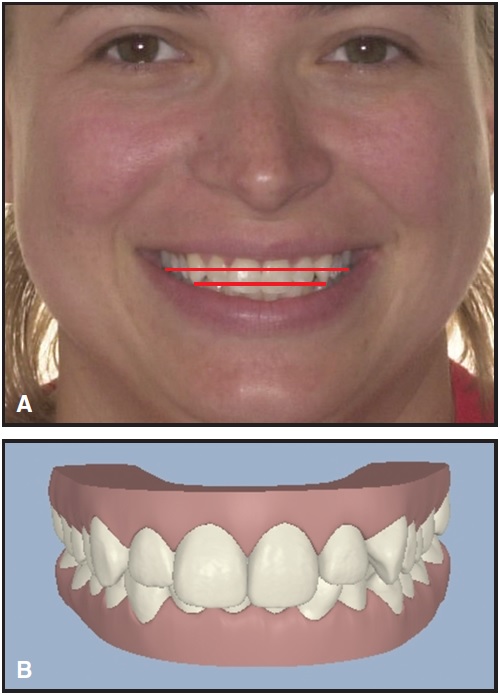
Fig. 12 A. Relationship of patient’s canine and first molar cusp tips noted on smiling facial photograph. B. Orientation of ClinCheck virtual model corrected to match occlusal plane in photograph (compare Figure 4).
Although not a perfect solution, it is a much better starting point for diagnosis than the current method of virtual orientation.
FOOTNOTES
- *Trademark of Align Technology, Inc., 2560 Orchard Parkway, San Jose, CA 95131; www.aligntech.com.
- **Cadent, Inc., 640 Gotham Parkway, Carlstadt, NJ, 07072; www.cadent.com.
- ***Ormco Corporation, 1717 W. Collins, Orange, CA 92867; www.ormco.com.
REFERENCES
- 1. Graber, T.M.: Incidence and recognition of malocclusion, in Orthodontics: Principles and Practice, 3rd ed., W.B. Saunders, Philadelphia, 1972, p. 226.
- 2. Downs, W.B.: Variations in facial relationships: Their significance in treatment and prognosis, Am. J. Orthod. 34:812-840, 1948.
- 3. Downs, W.B.: The role of cephalometrics in orthodontic case analysis and diagnosis, Am. J. Orthod. 38:162-182, 1952.
- 4. Baum, A.T.: Downs’ analysis template transparencies for application directly to cephalometric x-ray films, Angle Orthod. 22:224, 1952.
- 5. Braun, S. and Legan, H.L.: Changes in occlusion related to the cant of the occlusal plane, Am. J. Orthod. 111:184-188, 1997.
- 6. Romano, F.L.; Ramalli, E.L.; Tavares, S.W.; Pereira Neto, J.S.; Magnani, M.B.B.A.; and Nouer, D.F.: Comparison between cephalometrics measure using anatomic and metallic porion point, Braz. J. Oral Sci. 4:730-734, 2005.
- 7. Clinical Examination Guide, 2010-2011, available on ABO website: www.americanboardortho.com.
- 8. Andrews, L.F.: Straight Wire: The Concept and the Appliance, L.A. Wells, San Diego, 1989.
- 9. Uğur, T. and Yukay, F.: Normal faciolingual inclinations of tooth crowns compared with treatment groups of standard and pretorqued brackets, Am. J. Orthod. 112:50-57, 1997.
- 10. Ghaleb, N.; Bouserhal, J.; and Bassil-Nassif, N.: Aesthetic evaluation of profile incisor inclination, Eur. J. Orthod., published online August 17, 2010.
- 11. Sarver, D.: Soft tissue based diagnosis & treatment planning, Clin. Impress. 14:21-26, 2005.
- 12. Ackerman, J.L.; Proffit, W.R.; Sarver, D.M.; Ackerman, M.B.; and Kean, M.R.: Pitch, roll, and yaw: Describing the spatial orientation of dentofacial traits, Am. J. Orthod. 131:305-310, 2007.
- 13. Parekh, J.; Fields, H.; Beck, M.; and Rosenstiel, S.: The perception of selected aspects of smile esthetics—smile arcs and buccal corridors (abstract), Am. J. Orthod. 129:711, 2006.
-
 DR. PAQUETTE
Dr. Paquette is in the private practice of orthodontics at 8430 University Executive Park Drive, Suite 605, Charlotte, NC 28262; e-mail: davep@paquetteortho.com.