Digital Bracket Placement for Indirect Bonding
Indirect bonding was first described in 1974.1 As materials and techniques have evolved, more than 200 articles have been published on various procedures and improvements. Compared with direct bonding, indirect bonding generally improves accuracy2 and reduces treatment time.3 On the other hand, the laboratory time required to produce the trays can negate the gains in chairside efficiency.4
Before digital workflows were introduced, the indirect bracket-placement process involved multiple messy and time-consuming steps. Stone or resin models were fabricated, brackets were placed on the models with either a dissolvable material or a composite, and a transfer tray was created. Today, software can be used to precisely place brackets based on computer-aided measurements, greatly reducing lab time. Our in-office analysis has shown a savings in lab time of 21 minutes per patient for digital bracket placement over analog placement, in addition to eight minutes at the chair for indirect bonding over direct bonding. Not only does this approach improve the daily schedule flow, but it compounds efficiency through increased accuracy, by reducing the number of repositioned brackets and wire bends needed during treatment.
We have used the following digital bracket placement method for several months on more than 200 cases in our office. This article outlines the steps involved and the lessons we have learned from our development process, so that you can take full advantage of the digital technology now available.
Similar articles from the archive:
- Precision of Bracket Placement on Dental Models August 2009
- A New Bracket-Placement Device July 2008
- Ideal Appliance Placement with APC Brackets and Indirect Bonding September 1999
Procedure
To make best use of this technique, you need a three-dimensional scanner capable of generating stereolithographic (STL) files (we use the iTero Element*), a 3D printer (we use Form 2**), and OrthoAnalyzer*** software with Appliance Designer*** and Indirect Bonding Studio.† Also recommended is a MiniSTAR‡ thermoforming machine or its equivalent.
Scan the dentition: Use your preferred scanner to create an STL file. Import the files into OrthoAnalyzer through Communicate*** or from the desktop.
Prepare the scan (segmentation): The process of establishing the occlusal plane and defining the upper and lower teeth on the models starts with segmentation (watch the video below for a demonstration).
1. Indicate the mesial and distal marginal ridges of the posterior teeth and the mesial and distal incisal edges of the anterior teeth (Fig. 1A).
2. After the software outlines the tooth structures, define the gingival margins (Fig. 1B).
3. When segmentation is complete, modify and sculpt the tissue and teeth if needed (Fig. 1C). We rarely use this feature.

Fig. 1 A. Mesial and distal points indicated on posterior marginal ridges and anterior incisal edges using OrthoAnalyzer*** software. B. After software outlines tooth structures, user defines gingival margins. C. User can alter or sculpt tissues if needed.
Digitally place the brackets: The Indirect Bonding Studio workflow will guide you through the next steps.
1. Select the patient’s segmented model from OrthoAnalyzer, then select the bracket icon under the “Treatment” menu.
2. Set the facial axis points along the clinical crown lines (Fig. 2A), according to the six keys defined by Andrews.5 The facial axis points and clinical crown lines can be modified during the segmentation process, but we prefer to accept the defaults and then perform the final bracket positioning in Indirect Bonding Studio.
3. Choose either a bracket set†† for all teeth or single brackets for individual teeth (Fig. 2B). The selected brackets will then populate on the model (Fig. 2C). A red dot indicates a bracket that can be moved to your desired position.
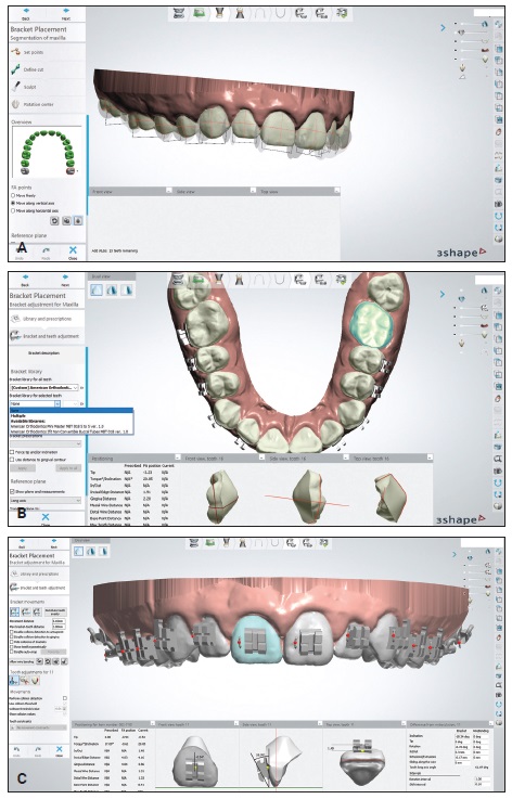
Fig. 2 A. Facial axis points determine where brackets appear in Indirect Bonding Studio.† B. Brackets†† can be placed as sets for all teeth or separately for individual teeth. C. Red dots indicate brackets that can be moved to desired positions. Dots turn green when user clicks double-lock icon to complete positioning (continued in next image).
The digital setup allows evaluation of the measurements from many angles at once as the brackets are positioned (Fig. 2D). We rely on the computer-measured incisal edge distance to ensure the most accurate leveling and occlusal coupling.
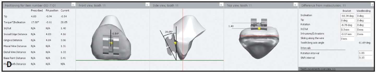
Fig. 2 (cont.) D. Close-up of bracket positioning with computer-aided design.
4. When you are finished positioning the brackets, select the double-lock icon on the left side of the screen. The dots should then turn green.
5. Validate the bracket positions and save the file (Fig. 3).
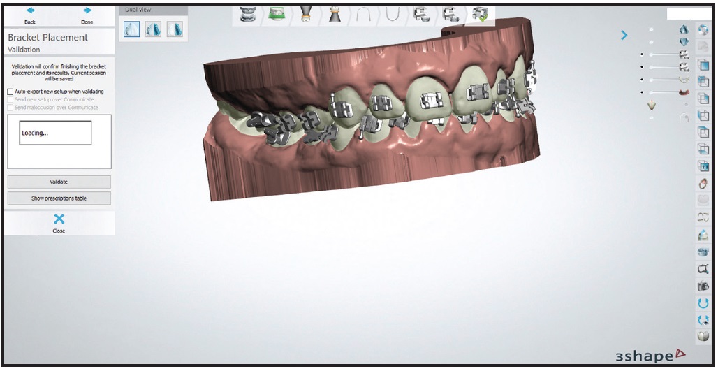
Fig. 3 Bracket position validated and saved using CD icon in upper right corner of screen. Note option to view prescription table of bracket locations, which can be used for future rebonding if needed.
Create the bracket transfer medium: Close OrthoAnalyzer and open Appliance Designer (watch the following video for a demonstration).
1. Open the Indirect Bonding Module and select the patient.
2. Create a new appliance by choosing the plus-sign icon in the top panel (Fig. 4). Name the appliance as desired. Select “Vacuum Pressed Transfer Media” as the production equipment.
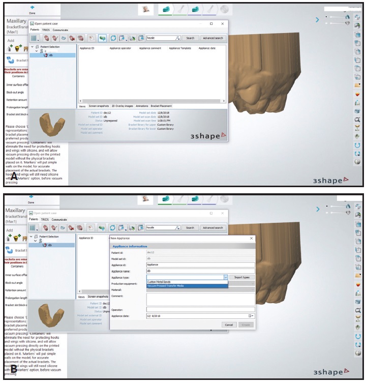
Fig. 4 A. Patient selected in Appliance Designer*** with Indirect Bonding Module. B. “Vacuum Pressed Transfer Media” selected for new appliance.
3. The model will load with the brackets attached (Fig. 5A). Choose the “Containers” tab, and set the block-out angle to −20° and the retention amount to .1mm. We recommend these settings after considerable trial and error. When we added more than .1mm of retention in the software, the bracket wings and hooks failed during printing and support removal. The −20° block-out angle provides an opening in the thermoformed indirect tray that is narrower than the bracket, thus adding a retentive feature for essential stability during the clinical procedure.
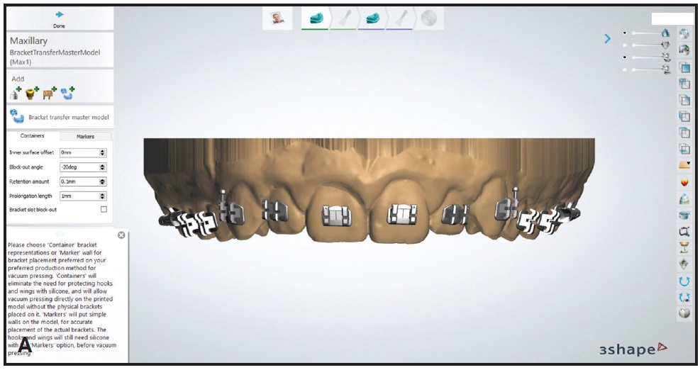
Fig. 5 A. Model with brackets attached. Block-out angle set to −20°, and retention amount to .1mm (continued in next image).
4. When the changes are confirmed, the bracket transfer medium model color will change, and the prescribed block-outs should be visible (Fig. 5B).
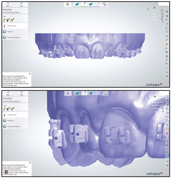
Fig. 5 (cont.) B. Bracket transfer medium model color changes after confirmation.
Print the models: Export the bracket transfer medium models from Appliance Designer to the desktop.
1. In the 3D printer software (we use PreForm‡‡), orient the models at about a 35° angle with the supports (Fig. 6). The goal is to have as few supports as possible on the bracket wings. Printing flat on the platform is not advised because of the need for small supports and the likelihood of distorting the bracket wings and hooks on the model.

Fig. 6 A. For best printing output, create setup with as few supports as possible on bracket wings. B. Printed model.
2. When the print is complete, wash the model in an isopropyl alcohol bath and then post-cure for two minutes.
3. Use a serrated, 1mm-thick disc in a lab handpiece to notch the incisal portions of the brackets on the model (Fig. 7). This creates more undercut and improves the retention of the thermoformed tray, so that the brackets will be held firmly in place while the bonding material is applied.
4. Create a thermoformed transfer tray from the model. We use flexible sheets of 1.5mm Bioplast‡ material in a MiniSTAR machine.
5. Cut away excess material from the tray and clean thoroughly with soap and water. If desired, cut the trays into quadrants or sextants. Delivering trays in quadrants allows unilateral isolation of the molars at the chair.
6. Insert the brackets that were used in the software setup into the thermoformed trays (Fig. 8). Make sure the retention is strong enough that the brackets are not easily displaced.
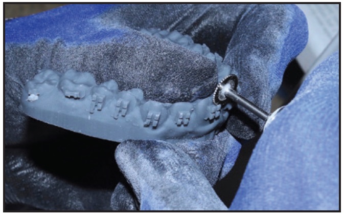
Fig. 7 Incisal portions of brackets notched with serrated, 1mm-thick disc to create more undercut and improve retention of thermoformed tray.
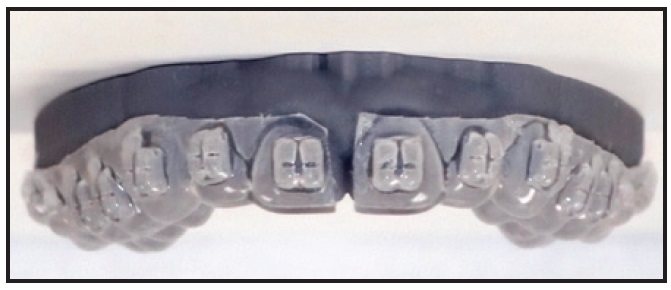
Fig. 8 Printed model with brackets and thermoformed transfer tray.
Deliver the indirect bonding trays: The remaining steps are performed at the chair.
1. Once the teeth have been isolated, etch them for 30 seconds. We use 3M self-etching primer§ on the posterior teeth if moisture control is a concern.
2. Add a dab of GC Ortho Connect§§ to each bracket base along the edges, with a dot in the center (Fig. 9A). GC Connect is a one-step primer and adhesive that we find ideal for this application because of its lower viscosity and higher bond strength compared with other bracket cements. The most important goal is to ensure that all sides of the bracket are sealed against the tooth, with minimal flash.
3. Seat the tray and light-cure for 12 seconds on each side (Fig. 9B). We use an Ortholux§§§ Luminous Curing Light with a 1,600mW/cm2 light-emitting diode.
4. Remove each tray by using a hemostat to tease it away from the gingivae above or below the brackets and then rolling it lingually (Fig. 10).
5. After the trays have been removed, test the bond strength of each bracket by applying finger pressure under the tie wing. We would rather the bracket fail at the chair than after the patient leaves the office.
6. Place the archwires and provide oral hygiene instructions.
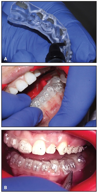
Fig. 9 A. GC Ortho Connect§§ cement applied to edge of each bracket base, with dot in center. B. Tray seated and light-cured for 12 seconds on each side.
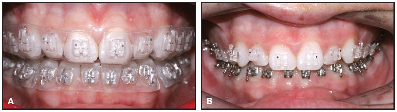
Fig. 10 A. Completed transfer tray and bonded appliances. B. Tray removed by teasing out with hemostat along gingivae above or below brackets and then rolling lingually.
Conclusion
Digital bracket placement for indirect bonding can be easily added to your workflow.5,6 Progressing from digital placement to conventional chairside delivery as described here will translate your treatment-planning data to the patient with minimal loss of detail. This technique allows the practitioner to benefit from the chairside efficiencies of indirect bonding while drastically reducing lab time. Moreover, the ability to efficiently fabricate indirect bonding trays can expand practice capacity and create a real return on investment for your digital equipment.
FOOTNOTES
- *Registered trademark of Align Technology, Inc., San Jose, CA; www.aligntech.com.
- **Registered trademark of Formlabs, Inc., Somerville, MA; www.formlabs.com.
- ***Trademark of 3Shape, Copenhagen, Denmark; www.3shape.com.
- †3Shape, Copenhagen, Denmark; www.3shape.com.
- ‡Great Lakes Orthodontics, Ltd., Tonawanda, NY; www.greatlakesortho.com.
- ††American Orthodontics, Sheboygan, WI; www.americanortho.com.
- ‡‡Formlabs, Inc., Somerville, MA; www.formlabs.com.
- §3M, Monrovia, CA; www.3M.com.
- §§Trademark of GC America, Inc., Alsip, IL; www.gcorthodontics.com.
- §§§Trademark of 3M, Monrovia, CA; www.3M.com.
REFERENCES
- 1. Newman, G.V.: Direct and indirect bonding of brackets, J. Clin. Orthod. 8:264-272, 1974.
- 2. Koo, B.C.; Chung, C.H.; and Vanarsdall, R.L.: Comparison of the accuracy of bracket placement between direct and indirect-bonding techniques, Am. J. Orthod. 116:346-351, 1999.
- 3. Haeger, R.S.: Analyzing clinical metrics of indirect bonding and self-ligating brackets, J. Clin. Orthod. 49:49-52, 2015.
- 4. Bozelli, J.V.; Bigliazzi, R.; Barbosa, H.A.; Ortolani, C.L.; Bertoz, F.A.; and Faltin, K. Jr.: Comparative study on direct and indirect bracket bonding techniques regarding time length and bracket detachment, Dent. Press J. Orthod. 18:251-257, 2013.
- 5. Andrews, L.F.: The six keys to normal occlusion, Am. J. Orthod. 62:296-309, 1972.
- 6. Thomas, R.: Indirect bonding: Simplicity in action, J. Clin. Orthod. 13:93-106, 1979.
-
 DR. LAYMAN
Dr. Layman is in the private practice of orthodontics at Straighten Up Orthodontics, 501 S. Missouri Ave., Clearwater, FL 33756; e-mail: drbill@suortho.com.

COMMENTS
.